FAQ OF THE MONTH
 APRIL 2024 APRIL 2024
QUESTION: Does AISI D114, Clip Angle Design Guide, require consideration of prying action when evaluating the anchored leg of a clip angle?
 ANSWER: AISI D114 provides design guidance based on both a strength limit state and a deflection limit state for clip angles subject to tension. ANSWER: AISI D114 provides design guidance based on both a strength limit state and a deflection limit state for clip angles subject to tension.
Traditional limit states associated with prying action are:
- Bending failure of the connecting element (e.g. anchored clip leg).
- Tension failure of the fastener.
However, based on the University of North Texas study on thin screw attached clips two additional strength limit states were identified and are addressed in AISI D114:
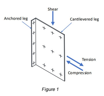
- Pull-over of the anchored clip angle leg (Figure 1).
- Pull-out of the screw from the base material.

The pull-over strength limit state, Pnov is defined as,
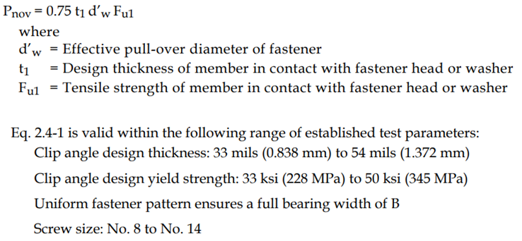
The pull-over strength design equation was calibrated to test results. Thus, any prying effects are included in the design equation. Therefore, prying effects need not be considered. But for the pull-out strength and screw tension strength evaluations, the prying effects should be considered.
The D114 deflection limit state is as follows:
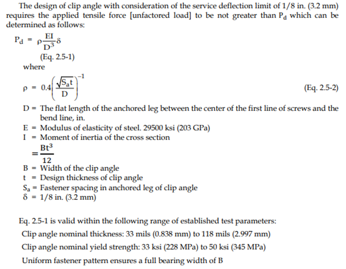
Based on the UNT testing, for thicker clip angles, the 1/8” deflection limit was achieved prior to a failure of the clip angle. Thus, when applying the AISI D114 design methods because a deflection limit is imposed for clip angles thicker than 54 mils the traditional prying action limit states are not a design consideration.
However, if the 1/8” deflection limit is not imposed as a design limit state, then prying action should be considered when evaluating the following limit states:
- Bending failure of the connecting element (e.g. anchored clip leg)
- Tension failure of the fastener
- Pull-over of the anchored clip angle leg.
- Pull-out of the fastener from the base material.
MARCH 2024
QUESTION: Why does AISI D114-21, Cold-Formed Steel Clip Angle Design Guide, not consider the bending limit state?
ANSWER: AISI D114 is providing design guidance. The design equations are not code adopted.
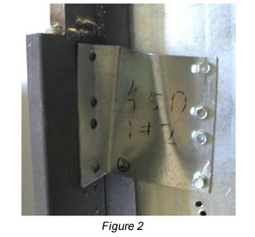
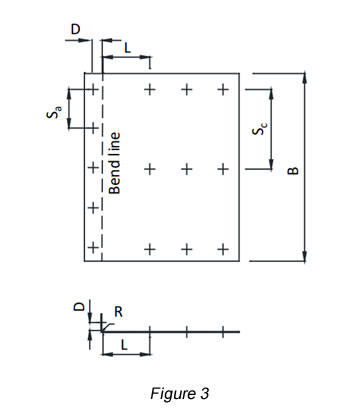
When subjected to a shear load (Figure 1), a clip angle is structurally analogous to a short cantilever beam. Based on research at the University of North Texas, the typical clip angle failure occurs in a panel of length L by depth B (Figures 2 and 3). Thus, the aspect ratio for the failure panel is defined as L/B.
A beam is generally regarded as a “deep beam” when its shear span-to-depth ratio, L/B, is < 2.0. Because a clip angle may typically have an L/B ratio equal to or less than 2.0 they exhibit behavior consistent with a deep beam. Also, as defined by AISI D114, the equations are limited to clips having L/B < 1.4.
The main difference between a shallow beam (typical floor joist or curtain wall stud) and a deep beam is that in the case of a shallow beam shear deformations are negligible and could be ignored while shear deformations must be considered in the analysis and design of a deep beam.
Because of the geometry of deep beams, their behavior is different from shallow beams. Deep beams are shear dominant and shallow beams are flexure dominant. Thus, the clip angle predominantly fails in shear rather than flexure because it has a small L/B ratio.
FEBRUARY 2024
QUESTION: My question pertains to strap splices in strap braced shear walls. Can we splice the strap itself? We have a large shear wall, and the client wants to splice the strap. Considering that these straps are loaded in tension, I would think a simple 24" long reinforcing strap of same width and gauge centered on splice and screwed on each side of the splice with enough screws to develop the full tension capacity of the strap or at least to develop the applied tension load per strap. Are there negative sides or issues with splicing straps?
ANSWER:  Splicing of a strap is not prohibited in either AISI S240, North American Standard for Cold-Formed Steel Structural Framing or AISI S400, North American Specification for the Design of Cold-Formed Steel Structural Members. However, both yielding and rupture at the splice connection will need to be considered. Also, if the design includes seismic forces, the splice design should be based on the expected strength of the straps, or the seismic force including overstrength, Ω0. Splicing of a strap is not prohibited in either AISI S240, North American Standard for Cold-Formed Steel Structural Framing or AISI S400, North American Specification for the Design of Cold-Formed Steel Structural Members. However, both yielding and rupture at the splice connection will need to be considered. Also, if the design includes seismic forces, the splice design should be based on the expected strength of the straps, or the seismic force including overstrength, Ω0.
JANUARY 2024
QUESTION: My purchasing department has been unable to obtain ASTM A1003. But A653 is readily available. May I use A653 for cold-formed steel members?
ANSWER: As discussed by CFSEI Tech Note G801, cold-formed steel framing was traditionally manufactured from galvanized, Galvalume® or Galfan® sheet steel complying with the requirements of ASTM A653, A792 or A875, respectively. One of the purposes of the ASTM A1003 standard was to provide a common standard for these various materials to simplify the process for the specifier and supplier.
ASTM A1003 was developed to be inclusive of the former ASTM A653, A792 and A875 standards, provide additional options for suppliers, and be consistent with the material requirements of the AISI S240, North American Standard for Cold-Formed Steel Structural Framing.
The AISI S240 Section A3.1 User Note states:
“ASTM A1003 was developed to be inclusive of ASTM A653/A653M, A792/A492M, A875/A875M and A1063/A1063M standards. For more information see CFSEI Tech Note G801. Therefore, products furnished to these material standards meet the requirements of A1003/A1003M.”
DECEMBER 2023
QUESTION: I have designed the hold-downs and anchorage of my shear wall for overstrength or expected strength. Do I now need to design the foundation for these elevated forces?
ANSWER: For designs using AISI S400, the hold-down and anchorage device are required to be designed with consideration given to overstrength.
However, In the United States and Mexico, for foundations, the required strength shall be determined from the seismic load effect and need not include the overstrength factor (Ωo) nor consider the expected strength of the seismic force-resisting system unless otherwise specified in the applicable building code.
The following User Note has been adopted for the next edition of AISI S400:
“In the United States and Mexico, the design of the foundation itself need not consider overstrength or expected strength. However, hold-downs and anchorage into the foundation are capacity protected components. Design of these components, including limit states associated with failure of the foundation material (e.g. concrete breakout, side face blowout, anchor pullout and pryout) must meet the required strength provisions of Section B3.”
A similar user note has not been adopted for the next edition of AISI S240 because S240 is limited to design for an R value of 3.
NOVEMBER 2023
QUESTION: I have a quick question regarding metal stud shear walls sheathed with OSB or plywood. When sheathing panels are installed with their long sides vertical, do panel joints need to be staggered?
ANSWER: The only requirement in AISI S240 applicable to this question:
- Section B5.2.2.3.1 (g) – All sheathing edges are attached to structural members or panel blocking, unless otherwise specified.
- Section B5.2.2.3.3 (b) – Wood structural panels are applied either parallel to or perpendicular to studs.
In AISI S400:
- Section E1.4..1.1 (k) – All sheathing edges are attached to structural members or panels.
S240 and S400 do not have a requirement.
However, good practice would recommend staggering joints no matter what orientation of the panels.
OCTOBER 2023
QUESTION: I am evaluating an existing metal building built in the 70s. I am trying to confirm what grade of steel was likely used for the cold-formed steel Z-purlins. Since they're 7" and 12 ga thick, I assumed they are at least 50 ksi yield strength. However, there may have been a different grade of steel available back then. I am just trying to see if that is a possibility.
ANSWER: The Metal Building Manufacturers Association has a technical publication that is intended to provide some ideas and insights into how a metal building can be retrofitted or reinforced. See page 12 for a discussion of the material properties for purlins and frames.
SEPTEMBER 2023
QUESTION: The AISI shear provisions only seem to cover screw capacities for steel-to-steel connections. I have a condition on a project where I need to check the shear strength of screws through gypsum board and into a cold-formed steel stud. Specifically, I have a track ledger that is placed directly against a wall with (2) layers of gypsum board. The screws attach through the track ledger, through the (2) layers of 5/8" gypsum board, and into the stud flange. The track is in direct contact with the gypsum board, not the stud. The track ledger is also receiving joists. Are there published values for this type of condition? I'd like to know even if it’s just (1) layer of gypsum board. Is this even a code-accepted connection? Any insight you have will be greatly appreciated.
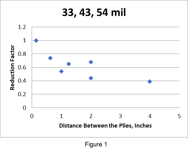
ANSWER: Currently the AISI Specification does not have criteria for the connection with material between the plies. Based on limited data regarding the connection behavior as illustrated by Figure 1, CFSEI Tech Note F602, Screw Connections with Other Materials or Gaps Between the Plies, was developed. The Tech Note provides design guidance regarding the evaluation of the strength of a connection.
AUGUST 2023
QUESTION: Is there a group fastener modification factor for multiple screws or are the attached cold-formed steel members considered rigid and all of the fasteners are considered equally loaded?
ANSWER: The equations in AISI S100 Section J4 are based on tests results. The assumption made when the test results were evaluated was that all of the screws shared the load equally.
JULY 2023
QUESTION: I am designing a parapet wall for a new project. I need help with the connection of a 362S162-54.
ANSWER: AISI D110-16, Cold-Formed Steel Framing Design Guide, offers some discussion regarding parapet walls. The discussion begins on PDF page 113. AISI D110 may be purchased at American Iron and Steel Institute Store.
Click here to purchase
|