2024 CFSEI DESIGN EXCELLENCE AWARD WINNERS
HONORABLE MENTION
SALAS O’BRIEN
DENVER INTERNATIONAL AIRPORT
CONCOURSE B EAST AND C EAST EXPANSIONS
DENVER, COLORADO
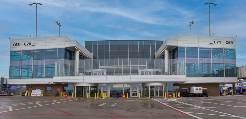 Denver International Airport Concourse B East and C East Expansions Denver International Airport Concourse B East and C East Expansions
9100 Pena Blvd
Denver, CO 80249
Completion Date: Fall 2022
Construction Cost: $3.8 Billion
Owner: City and County of Denver.
Architect of Record: Andy Hoef, Jacobs.
Engineer of Record for Structural Work: Lee Maggert, P.E., Jacobs.
Cold-Formed Steel Specialty Engineer: Russ Leffler, Salas O’Brien.
Cold-Formed Steel Specialty Contractor: Steve Chambers, Four Star Drywall.
Award Entry Submitted by: Daniel Stadig, P.E., Salas O’Brien.
Project Background
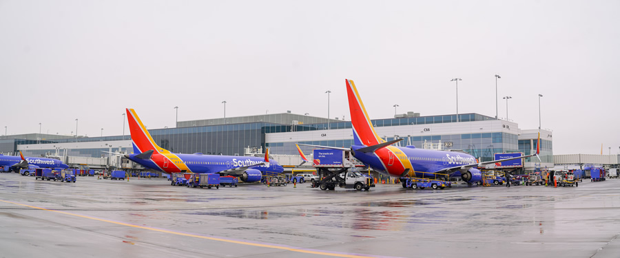
The Denver International Airport is of one of the world's busiest airports and a hub for air travel across the US and abroad. Denver undertook a large expansion project to expand two of their three concourses, Concourses B and C, by adding 126,000 square feet and 530,000 square feet to the east end of each concourse with estimated construction costs of $209 million and $878 million respectively.
The Concourse structures are built on drilled pier foundations and have structural steel superstructures. The exterior of the buildings is a mix of metal panel spandrel framing above and below the curtain wall.

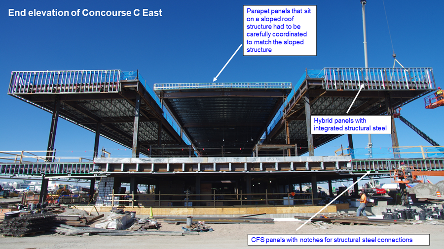
Salas O’Brien provided exterior engineering and panelization design assist and coordination services. Salas O’Brien also provided interior non-structural cold-formed steel (CFS) engineering and BIM services for this expansion.

Design Challenges and Solutions
Notable CFS engineering challenges included creating an exterior hybrid panelized system, engineering large exterior ceilings and soffits under a concourse bridge and around the apron and the overall quantity of unique framing conditions throughout the interior and exterior of the expansion.
The exterior panelization presented unique detailing and subsequent engineering challenges. The spandrel panels above the glazing may look standard from afar and in photos, but they were coordinated to integrate previously designed and detailed supplementary steel within the assemblies.
During initial coordination, the project team requested a prefabricated facade solution. The original design did not account for this, and structural steel detailing created several penetrations and interruptions that would not allow an efficient panel solution.
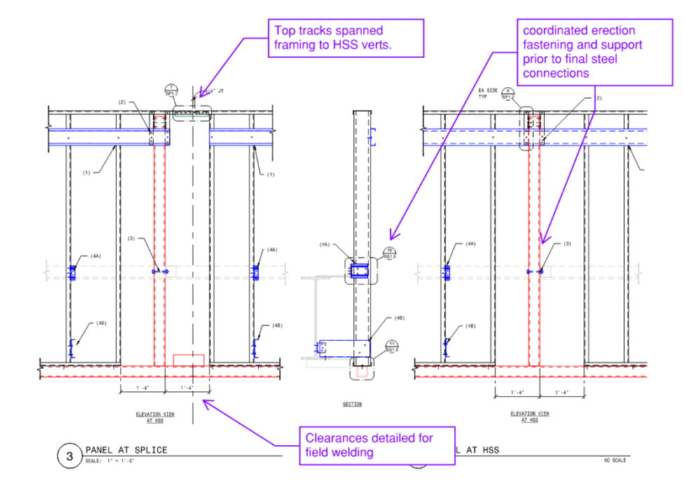
Additionally, CFS framing needed to be kept away from critical connection locations to allow field welding of the steel. These “no-fly” zones were typically the standard CFS anchorage locations to the steel. So, modified connection detailing was required.
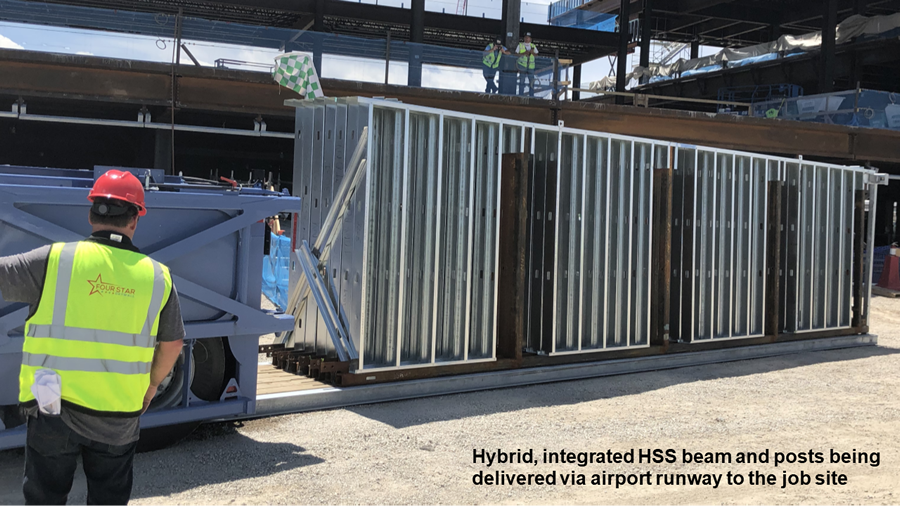
To address this challenge, Salas O’Brien created hybrid panels, coordinating the structural steel within the CFS panels to allow reasonable panel sizes and execution. They were specifically detailed to work around and with the structural steel, such as posts, beams, knife plates and ledgers. The resulting exterior panel system consists of a wide variety of CFS and CFS/steel hybrid panels.
The roof steel could not be placed within the parapet panels, requiring specialty connections and panel configurations to work around the steel while allowing tolerance of the other trade’s installation.
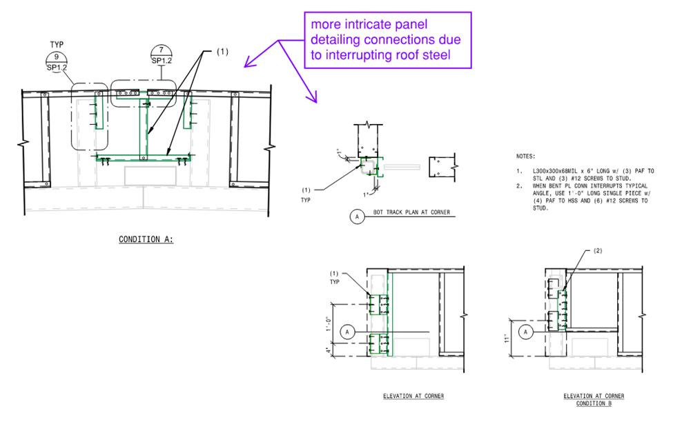
Additionally, a large cornice plate supplied by another trade needed to be coordinated and integrated into the parapet panelization. The cornice steel was long, enabling Salas O’Brien to develop a panel-to-panel connection that allowed for its expansion without damaging the framing.
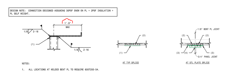
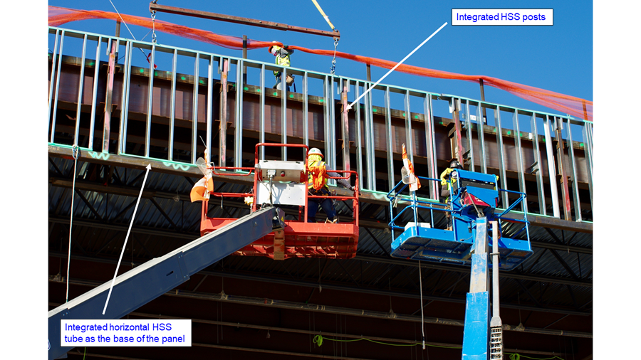
The successful execution of this system minimized the CFS trade's envelope impact on airport operations and allowed faster enclosure. Our ability to coordinate with the design team and other trades to provide a prefabricated installation proved the CFS team to be an invaluable partner serving this project.
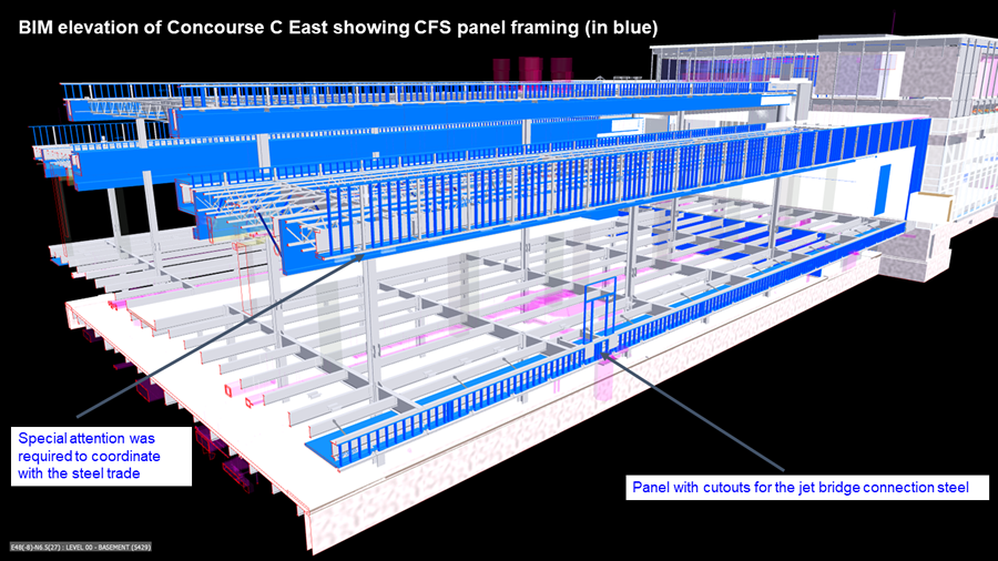
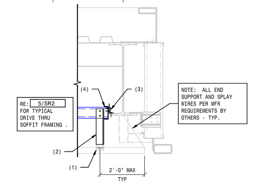
The exterior ceilings and soffits might have been simple if the chosen cladding system used standard sub girts to allow a typical CFS layout beneath to work. However, the sold product required exact anchorage points for the panels, which fell in expectedly difficult discrete locations to coordinate.
The design team required a CFS framed system with standard shapes and would not allow a proprietary hung support system to be substituted.
A CFS beam system with CFS angle struts was designed to work with the restrictive cladding system’s clip and spacing requirements. Anchorage to the floor slab above was not allowed, so all beams had to coordinate between steel anchorage locations.
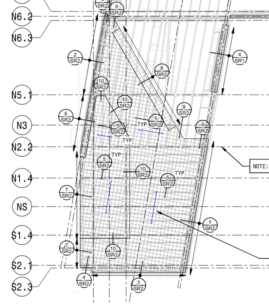
The plan view below illustrates the amount of required span direction changes and special detail conditions at the drive thru ceiling.
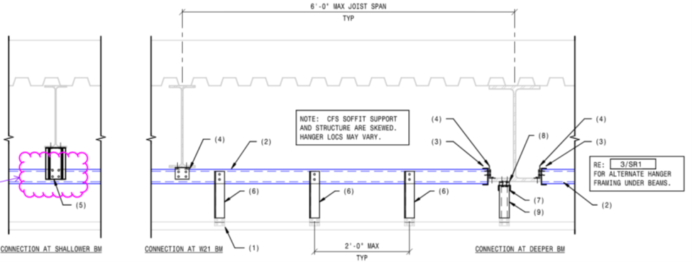
The design needed flexibility to work for the exact anchorage locations in the field and allow easy adjustment when necessary.
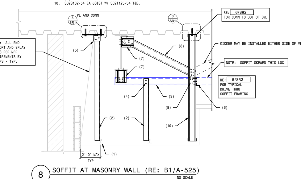
Although the SER did not want any anchorage into the floor slab above, some edge detailing required it nonetheless.
The remaining CFS design and detailing of exterior and interior portions of the expansion are difficult to envelope into single topics for discussion. But there were large amounts of miscellaneous locations where CFS framing was required to finalize incomplete design to configurations that did not work as detailed by the design team.
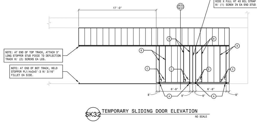
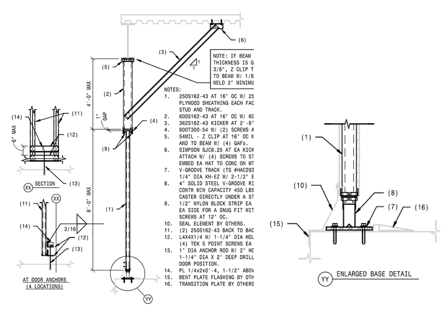
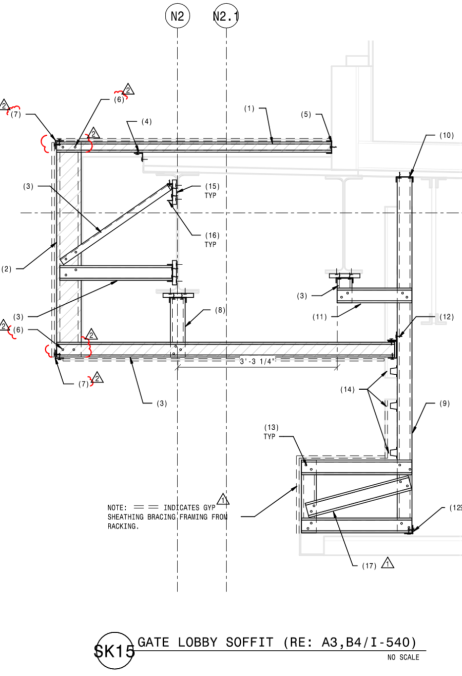
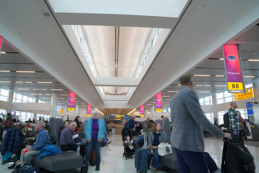
One unique example of a sliding temporary wall is shown below and an example of some of the interior soffit design Salas O’Brien performed.
A temporary opening was required to also function as a sliding door. Salas O’Brien designed a CFS temporary exterior wall that also acted as a sliding door.
Large interior soffits with intricate load paths required design and detailing assistance.
Concluding Remark:
Large public projects at operational facilities require the flexibility and dynamic nature of CFS framing and off-site construction to turn the architect’s vision into reality while meeting code and schedule requirements.
The DIA Concourse Expansion project exemplifies CFS framing’s necessity and key role in bringing this vision to 100% completion.
|