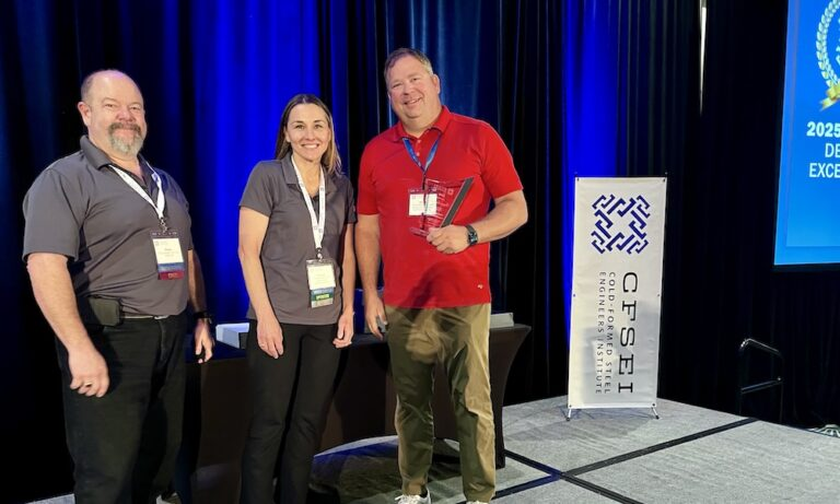
2025 CFSEI DESIGN EXCELLENCE AWARD WINNER

FIRST PLACE - COMMERCIAL
ENSIGN ENGINEERING & LANDING SURVEY, INC.
ONSET FINANCIAL HQ – ST. GEORGE, UTAH
ST. GEORGE, UTAH
 Onset Financial HQ - St.George, Utah Onset Financial HQ - St.George, Utah
1495 South Dixie Drive
St. George, Utah 84770
Completion Date: 2024
Construction Cost: $38 Million
Owner: Onset Financial HQ - St. George, Utah.
Architect of Record: Pierre Langue, AIA, Axis Architects.
Engineer of Record for Structural Work: Matthew Jackson, MJ Structural Engineers.
Cold-Formed Steel Specialty Engineer: Marlow M. Vasquez, P.E. & Quinn T. Lythgoe, P.E., Ensign Engineering & Land Surveying, Inc.
Cold-Formed Steel Specialty Contractor: Jared Noa, Pete King Corp.
Award Entry Submitted by: Scott B. Roche, P.E., S.E., Ensign Engineering & Land Surveying, Inc.
Project Background

The 55,000-square-foot Onset Financial headquarters in St. George, Utah, seamlessly integrates with the natural desert landscape and offers striking views of Snow Canyon’s neighboring peaks for its employees.
This four-story structure’s thoughtful design incorporates subtle shifts in the floor orientation, creating distinct building elevations on every level. The exterior features zinc metal panels paired with an aluminum curtain wall with high-performing glazing system, which enables durability and energy efficiency in the region’s extreme climate.
To achieve the project’s architectural vision, Ensign Engineering and Land Surveying, Inc. (Ensign) and Peter King Corp. collaborated closely to deliver a custom cold-formed steel (CFS) stud design that met the complex structural and aesthetic demands of the design team. This coordination ensured the execution of a façade that is as functional as it is visually compelling.

Design Challenges and Solutions
The unique building elevations of the Onset Financial headquarters posed significant challenges. The design features angled walls, isolated walls, ribbon windows, large soffits, expansive curtain wall systems and non-stacking floors, all of which required careful consideration of the façade’s load path. The façade needed to accommodate vertical deflection and lateral drift while maintaining the structural integrity of the secondary structure. Coordination with the design team and contractor was key to the project’s success.
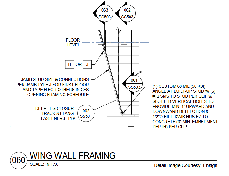
One notable challenge involved the sloped walls throughout the building elevations. These walls required special design considerations, as vertical studs within the sloped portions had to be vertically supported by the floor above. Adjacent non-sloped walls were ground-supported, creating vertical joints between the two sections.
To address this, the sloped bottom track of the wall used a custom vertically slotted clip connection as shown in Detail 060. This connection proved out-of-plane support for the track while allowing vertical differential movement between the sloped and non-sloped wall sections. This solution facilitated typical and efficient construction throughout the project and provided an economical approach for the sloped wall areas.

Another significant challenge occurred at the glazed walls on each building. The two-story sloped side pop-outs at these large windows required vertical studs on three sides in areas that extended beyond the building’s floor system. Crucial coordination with the architect and structural engineer ensured proper support for the CFS framing.
Wide-flange beams were extended past the floor with custom bend plates to support the CFS framing on all three sides of the pop-out, significantly simplifying the installation of the stud wall. While bend plates are typically used as pour stops for concrete floors, in this case, they solely supported the steel stud walls.
Successful collaboration between Ensign and Pete King Corp. ensured the issues were resolved before the CFS installation, minimizing on-site adjustments.
 Additional challenges emerged above the large, glazed walls. Because the windows were set inward from the building edge, no perimeter beam was available to support the top of the glazing. Additional challenges emerged above the large, glazed walls. Because the windows were set inward from the building edge, no perimeter beam was available to support the top of the glazing.
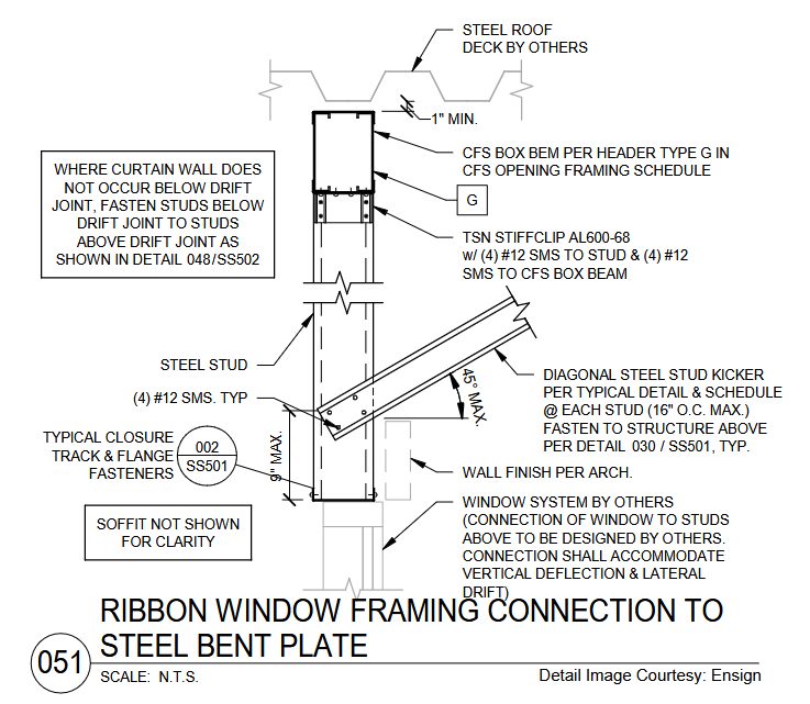
Ensign addressed this by designing a kicked drop stud to support both the aluminum panel fascia and the glass glazing (see Detail 051). Since the stud could not hang from the metal deck above, a CFS box beam was designed to span between perpendicular wind-flange beams.
This detail ensured an uninterrupted load path from the glazing system through the CFS structure to the primary steel, with the box beam positioned slightly below the metal deck to accommodate differential deflection.

The building’s exterior incorporates balconies with sweeping views, thoughtfully designed to connect employees with the outdoors. However, these balconies presented another design challenge.
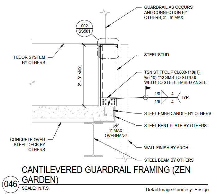
The initial design of the railings called for a cantilever stud wall supported only at the balcony floor level, with a glass railing attached to the top of the cold-formed steel wall. The total wall height of the assembly was approximately 5’-6”, and due to the varying slope and height of the stud wall, using HSS tubes for support was not feasible.
Instead, a moment-resisting connection to the concrete deck was required. Initially, the clips were directly anchored into the concrete deck, but the connection capacity was insufficient. After further coordination with the design team, the SEOR was able to provide embed plates to weld to the CFS studs, ensuring the system could adequately support the stud and glass railings. Detail 046 illustrates this unique design solution, showcasing the success of team collaboration.

This project required innovative solutions to address complex design challenges. Understanding the role of CFS in the overall design was crucial in meeting site-specific requirements. Through close coordination and creative problem-solving, the team successfully delivered a structural CFS wall system that met the project’s unique façade design and performance criteria.


|