2022 CFSEI DESIGN EXCELLENCE AWARD WINNERS
FIRST PLACE – RESIDENTIAL/HOSPITALITY
CLARKDIETRICH ENGINEERING SERVICES, LLC – SELFHELP FREEPORT
SENIOR HOUSING, FREEPORT, NEW YORK

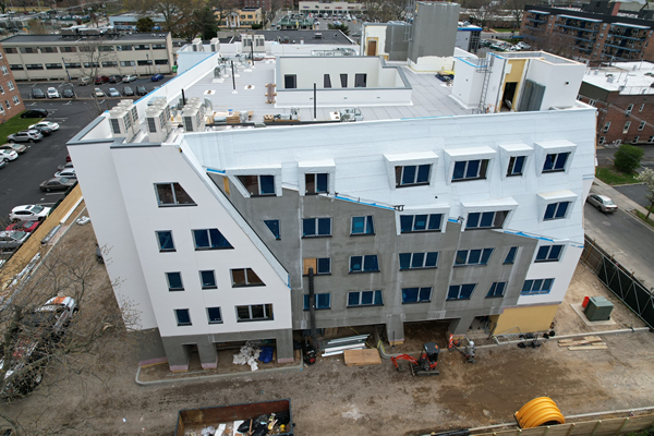
Selfhelp Freeport Senior Housing
81-83 South Bergen Place
Freeport, New York 11520
Framing Completed: 2021
Owner: Selfhelp Community Services
Architect of Record: Neil Cook, AIA, ASLA, Studio Libeskind
Engineer of Record for Structural Work: William Faschan, LERA Consulting Structural Engineers
Cold-Formed Steel Specialty Engineer: Lynn Padgett, P.E., ClarkDietrich Engineering Services, LLC
Cold-Formed Steel Specialty Contractor: Mitchell Blonder, Level 5 Carpentry Corporation
General Contractor: Michael Rogers, Procida Construction Corp.
Award Entry Submitted by: Lynn Padgett, P.E., ClarkDietrich Engineering Services, LLC
Project Background
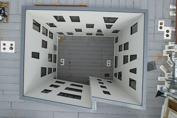
Selfhelp Freeport Senior Housing is an affordable senior living residence serving a low-income population. The building has 44units, community space, on-site services, center courtyard and rooftop terrace with a walking track. The building structure is four levels of cold-formed steel loadbearing light steel framing (LSF) over a second-floor concrete podium parking structure. The LSF framing utilizes 600S loadbearing interior walls, exterior LSF box and HSS edge girders on LSF beam pocket posts, exterior sloped 600S bypass walls, 1000S floor and roof joist with a 9/16" x 22ga form deck and a two-pour Dura-Cap self-leveling gypsum floor topping with acoustic mat, a rigid insulation and membrane roof with a combination of paver pedestals and a green roof system. The exterior wall system is a combination of 600S joist bearing vertical studs and sloped non-loadbearing bypass studs. The sloped exterior walls include window openings with dormers and are supported by floor and roof edge girders.
Design Challenges and Solutions
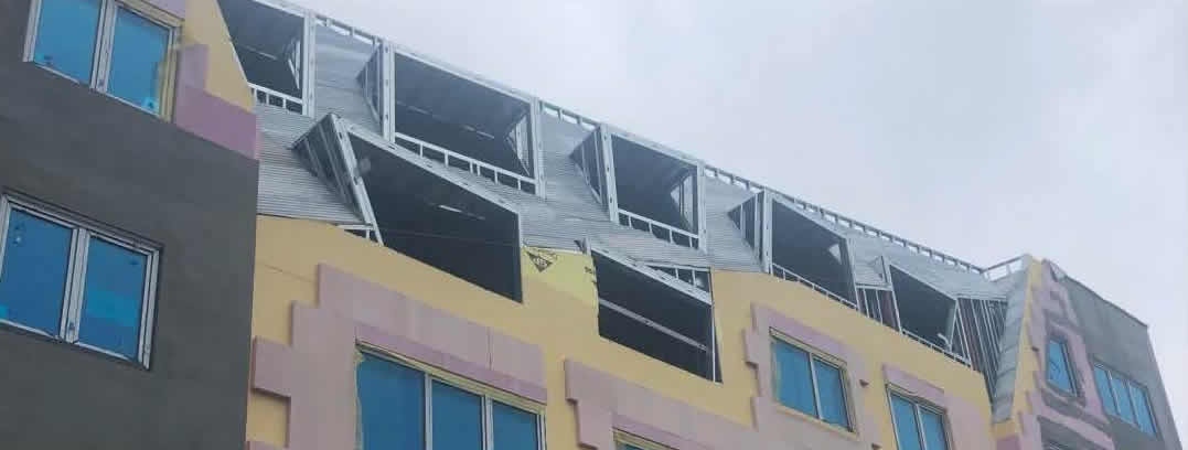
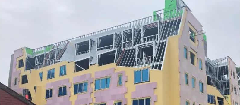
Due to the three-dimensional slope of the walls and wall openings, some exterior non-loadbearing walls require a break-shape wall track and two-angle HSS welded columns. Staggered exterior loadbearing wall openings along with trapezoid windows require oversized headers to align jambs. Infill framing between head and sill is installed for the shifting/trapezoid windows. Some wall openings could not avoid large post loads over the opening and exceed the capacity of an LSF header, and HSS tube bearing on a jack stud was designed and installed. Lateral stability is a mix of reinforced CMU stair and elevator towers along with LSF X-brace shear walls. Shear loads are calculated for both flexible diaphragm and rigid diaphragm and envelope the design for the worst-case shear wall and diaphragm loading. Due to building layout, some shear walls do not align in the fifth level and require a shifted shear wall with additional diaphragm connection details. LSF floor and roof diaphragm connections to the CMU are designed and installed according to loads provided by the engineer of record (EOR). X-Brace shear wall connections to the podium required cast-in-place embedment plates by the EOR. Hold-down connections to the embeds are by ClarkDietrich Engineering.
The Selfhelp Freeport project did not require building information modelling (BIM) by the LSF designer or the mechanical, electrical and plumbing designers, but the architect designed a very effective model of the building and accommodated a significant amount of coordination between the LSF specialty engineer, the general contractor and the LSF framing contractor. Layout for sloped wall intersections, edge girders, openings and posts would not have been accurately determined without the correct model and coordination initiated by the architect.
The general contractor successfully oversaw coordination for several expected conflicts between building components, such as the correct placement of shear wall embedment plates on the podium; MEP locations relative to bearing walls, posts, girders, and shear walls; three-dimensional exterior wall and opening conflicts with loadbearing framing and maintaining the architect's aesthetic intent; a sloped wall framing mock-up; and utilization of HSS headers and girders where LSF components were not practical.
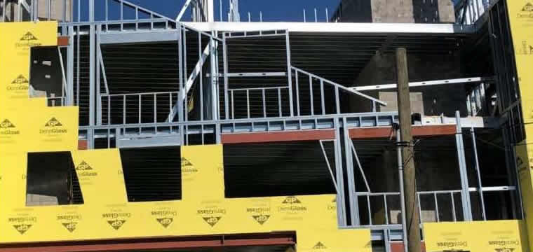
The framing contractor successfully erected this complex framing by participating and sometimes initiating coordination between the GC, architect and LSF specialty engineer, and then proceeding with construction after fully understanding the intent of the LSF plans and details. If material was difficult to procure, the contractor reached out to ClarkDietrich Engineering for an approved alternate component or detail. If the detail was difficult to understand, the framer reached out to ClarkDietrich Engineering to review and confirm the requirements before beginning work on the assembly. A key aspect to the success of this project was the direct line of communication between the field superintendent and the LSF specialty engineer which usually occurred in advance of installation, allowing the LSF specialty engineer time to consider the issue and develop a well-planned and coordinated response or revision. Material utilization was another part of this project managed very well. By way of value engineering, some posts, jambs and other high-load components were not designed with multi-ply on-center studs and track. Instead, these components utilized longer leg track, deeper flange studs or even Heavy-Duty Studs (HDS). These components must be ordered correctly, sometimes with longer lead-times, managed at delivery and on-site, and then installed correctly as detailed. To the best of my knowledge, the project material utilization and logistics were excellent. When that part of the project is correct, it is much easier to stay focused on the installation and detail accuracy.
Architectural Features Impacting the LSF Design
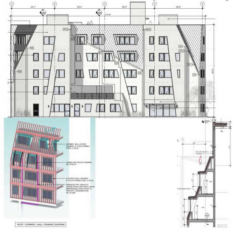
LSF – Two-dimensional sloped exterior wall framing.
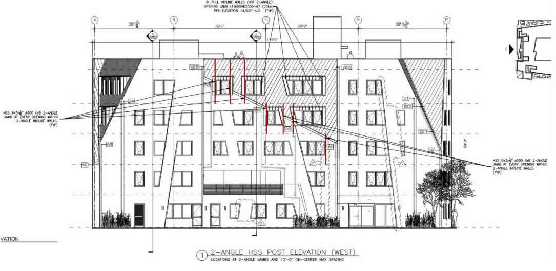
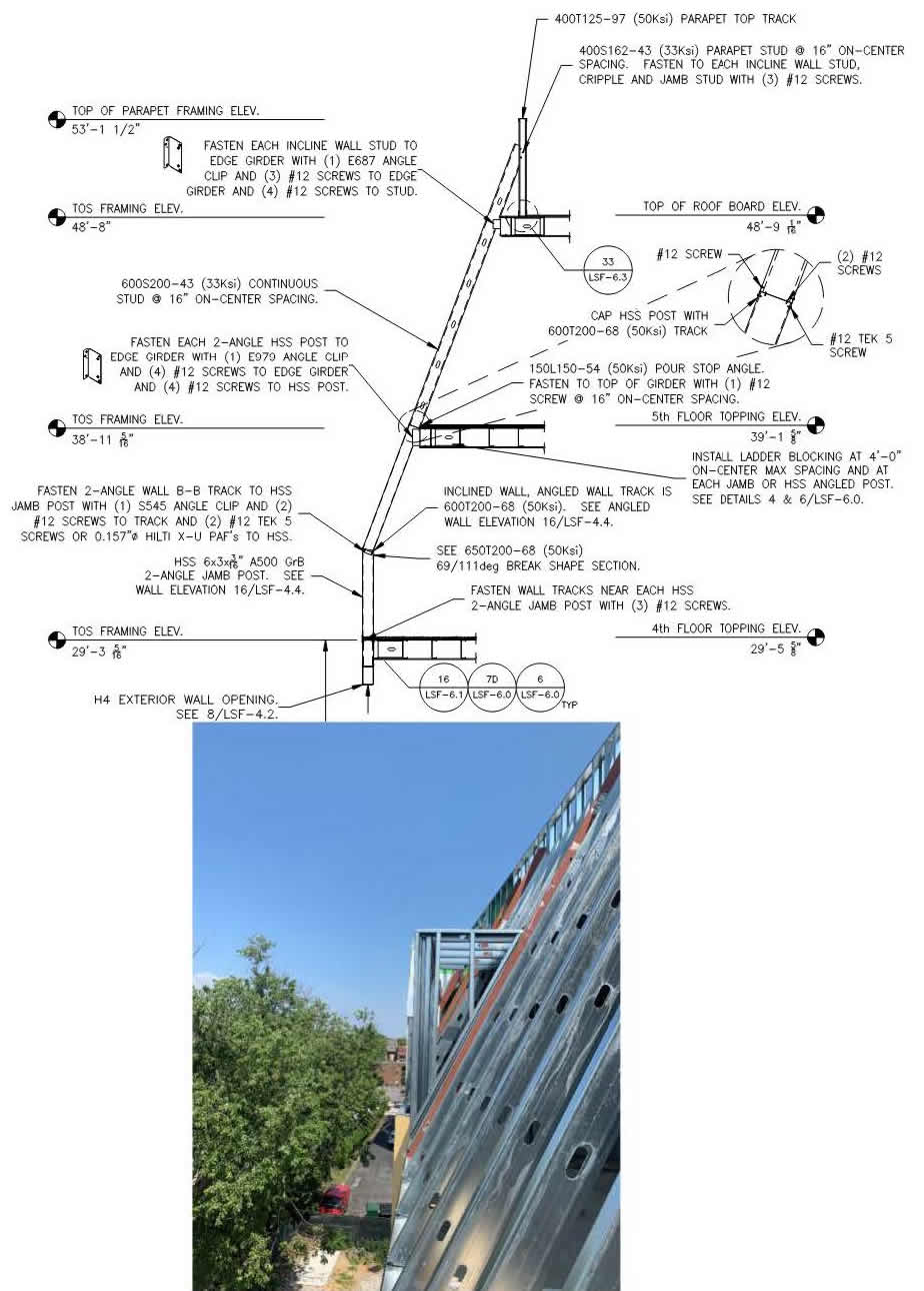
ClarkDietrich designed two-angle HSS jambs at each opening where the exterior wall has a two-angle sloped wall track requiring lateral support. The two-angle wall track was designed to span a maximum of 10 ft. between the HSS two-angle welded columns.
Overall elevation showing where two-angle HSS columns are required.

LSF framing elevation showing the required two-angle sloped wall break-shape track, two-angle HSS required size and weld, and connections from the two-angle break-shape track to the HSS jambs.
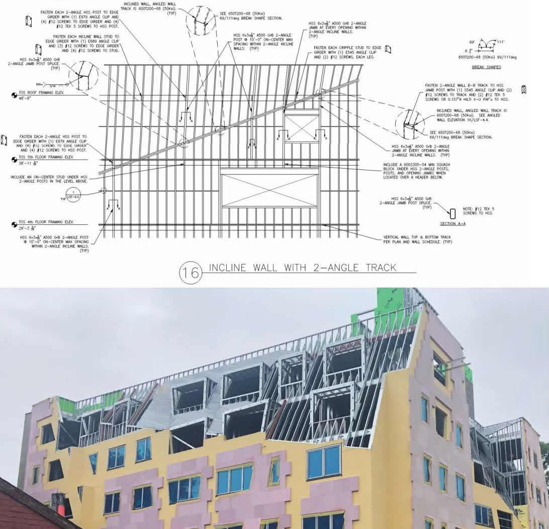
LSF wall sections showing the floor and roof edge girders, two-angle HSS posts and connections to the edge girders, and sloped LSF wall framing connections to edge girders.
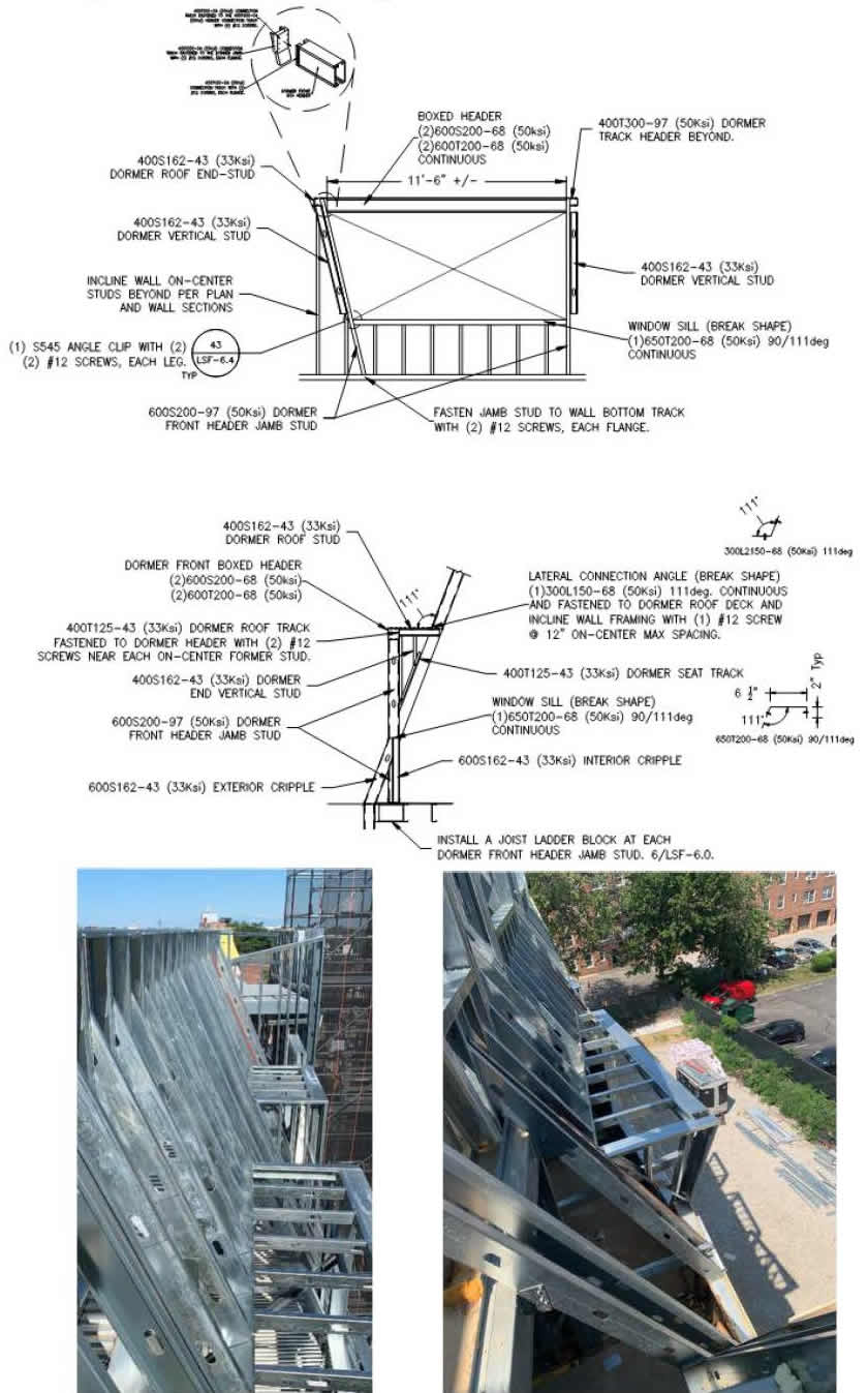
LSF sloped window dormer framing – as built.
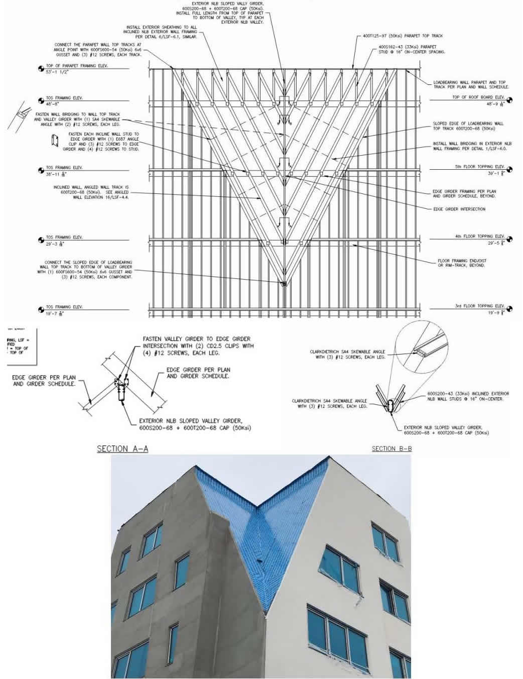
LSF three-dimensional sloped exterior corner framing.
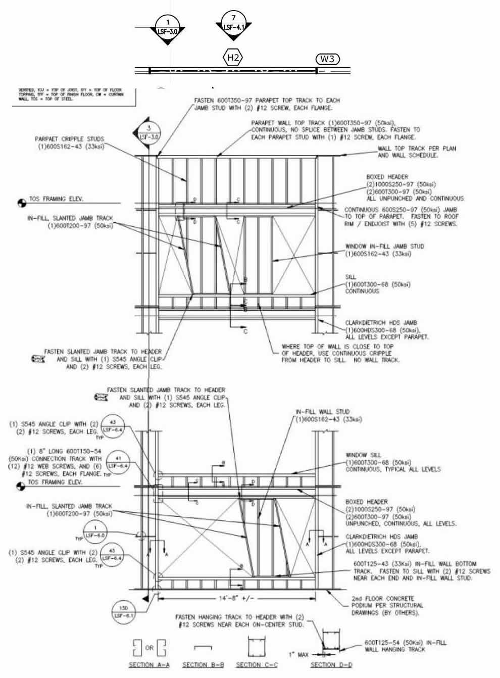
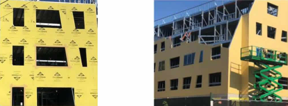
Architecture - Staggered trapezoid windows in joist-bearing exterior framing.
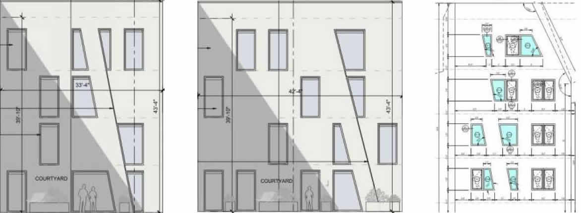
LSF – H-2 oversized window framing with infill trapezoid window rough openings.
Architecture - Fifth level bearing walls, posts and shear walls not aligning with the second- through fourth level bearing walls. (No image – see Architect Plans.)
LSF – Design the fifth-floor framing to support the offset fifth level bearing walls, posts and
shear walls. Plan notes indicate areas where additional floor framing and details are required.
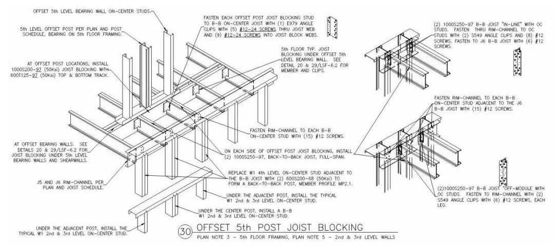
Heavy LSF joist components, blocking and uplift connections are designed and detailed.
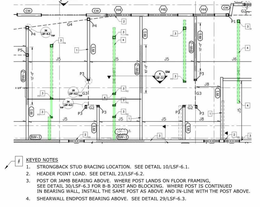
LSF – Fifth level bearing wall and post supported in the fifth-floor framing.
LSF – Fifth level shear wall end post supported in the fifth-floor framing.
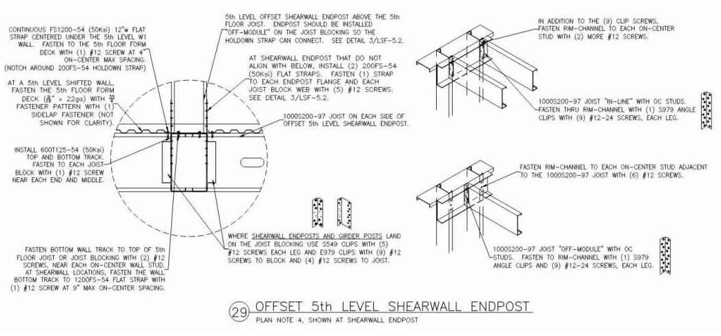
LSF – Fifth level shifted shear wall and fifth-floor diaphragm connections.
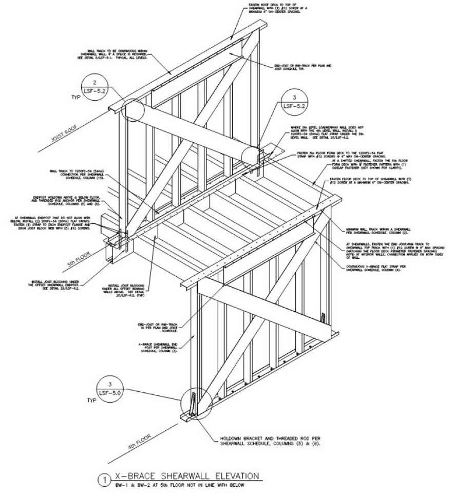
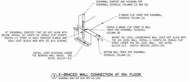
LSF – Fifth level shifted shear wall and fifth-floor diaphragm connections.
General Contractor and Framing Contractor Installation Excellence
The initial LSF design kickoff and coordination with the GC, framer and MEP installers included a summary of the differences between this ledger framed cold-formed steel joist and wall system relative to the building systems with which they were more familiar. Discussion items included: vertical pipe in stud cavity penetrating only wall track instead of coring through concrete, utilizing joist rim-track as a load-distribution member or header, penetrating rim-track with in-line framing only, form deck diaphragm and working surface, non-loadbearing trades following rough framing, MEP trades following non-loadbearing, floor topping poured after MEP and dry-in, and utilization of HSS components within the LSF assembly. All portions of the construction team embraced the building system and proceeded with confidence.
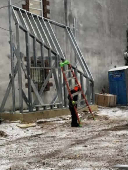
Early in the project, maybe even before receiving the LSF specialty engineering, the GC and framing contractor took the time to construct a two-angle sloped wall mock-up. This exercise highlighted the difficulty and the required attention to detail while working on the ground instead of trying to develop the technique during the actual building construction. After receiving and studying the LSF drawings, implementing the LSF plans, and details were clearer due to the installation experience gained during the mock-up framing exercise.
Utilization of HSS headers and two-angle HSS post framing was required within the LSF framing. Some project general contractors automatically push this work to the structural steel installer, and it can create scope-of-work and material procurement overlap and complication. The GC asked the architect to assist in determining the two-angle HSS locations, lengths, and angle points (only possible due to the architect’s 3-D model accuracy), then procured the shop-fabricated HSS components and allowed the framing carpenters to install the HSS components within the LSF specialty engineer’s designed configurations. This enhanced coordination with ClarkDietrich Engineering and resulted in the correct application of the HSS header and sloped wall components.
HSS two-angle jambs within LSF assembly.

HSS headers for oversized openings and point loads from above.

HSS edge girder details and weldable mount provisions for elevator door slide rails.

Architect 3-D Model and Coordination Excellence
The architect took a hands-on approach to reviewing the LSF delegated design drawings and assisting the GC to establish LSF component locations. Edge girder and sloped wall framing locations were very difficult to determine. So, the GC and architect used a 3-D model to clarify edge girder and post locations, and then presented it to the framer for correct installation.
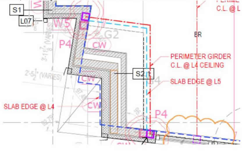
With the architect’s leadership, the design team was able to identify conflicts with windows and other angle points. After coordination, the LSF delegated designer was able to create accommodating details.

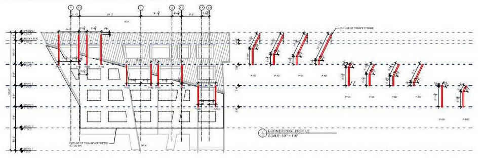
Due to the 2-D and 3-D exterior wall slope, the architect used the 3-D model to determine the HSS two-angle post bend locations. According to the LSF delegated design drawings, the architect created a Dormer Post Profile summary for each side of the building. This enabled the GC and framer to procure the welded two-angle HSS posts shop fabricated and ready to place in the wall without trying to locate, measure and fabricate on-site.
Summary
ClarkDietrich was initially brought into the project by Procida Construction to provide LSF structural recommendations and design assistance in an attempt to drive cost out of the building. Of course, the first few recommendations were to align more walls in the fifth level for shear wall locations, eliminate the 3-D intersections between sloped exterior walls, and remove the trapezoid window dormers at these sloped intersections. Some other areas were simplified, but these big recommendations were discarded, and the project proceeded as generally designed. I must admit that I am glad we kept the architectural design relatively unchanged. If we had eliminated these difficult areas, the project would not have been as unique and interesting.
All participants understood the level of complexity and were diligent about staying in communication and coordinating the difficult areas. The GC and framer accepted the integration of HSS into the LSF assemblies. The architect and EOR were accommodating to non-typical details and complex coordination. It is my opinion that the 3-D architectural model was required for the completion of this framing. The project success was especially tied to the willingness of the entire team to get together and resolve the complex design elements step-by-step without being overwhelmed.
|