2021 CFSEI CREATIVE DETAIL AWARD WINNERFIRST PLACECLARKDIETRICH ENGINEERING SERVICES LLC - PORSCHE LINCOLNWOOD LINCOLNWOOD, ILLINOIS
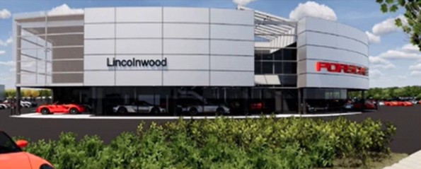
Porsche Lincolnwood Owner: Loeber Motors Project BackgroundAs a renovation to an existing Porsche car dealership, this project included some new exterior cold-formed wall and soffit framing, as well as some interior framing, all of which was designed by ClarkDietrich Engineering Services (CDES). The frameless glass aspect of the interior framing presented the most design challenges and is the focus of this submission. Design Challenges and Solutions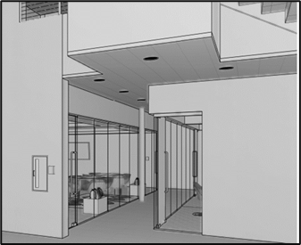
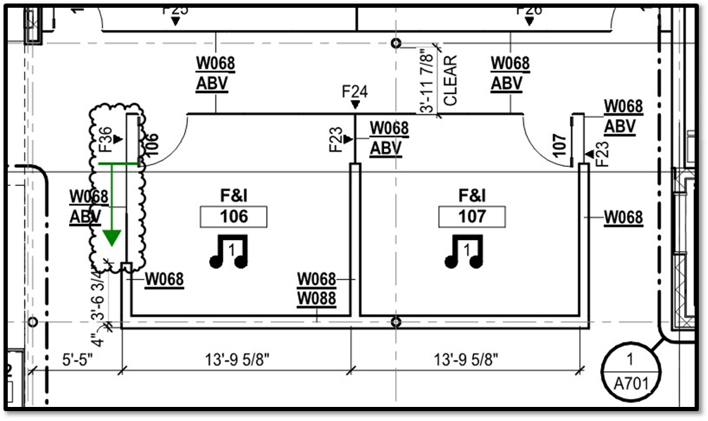
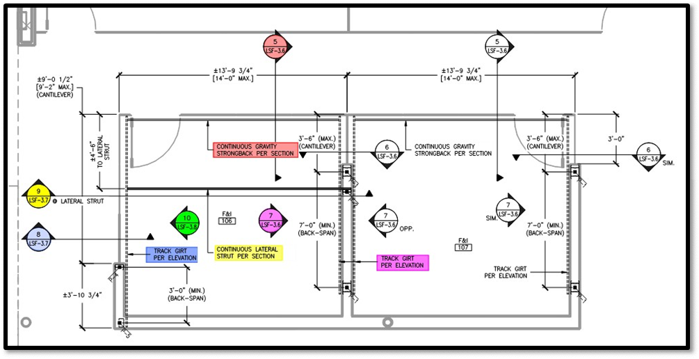
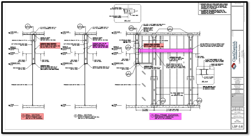
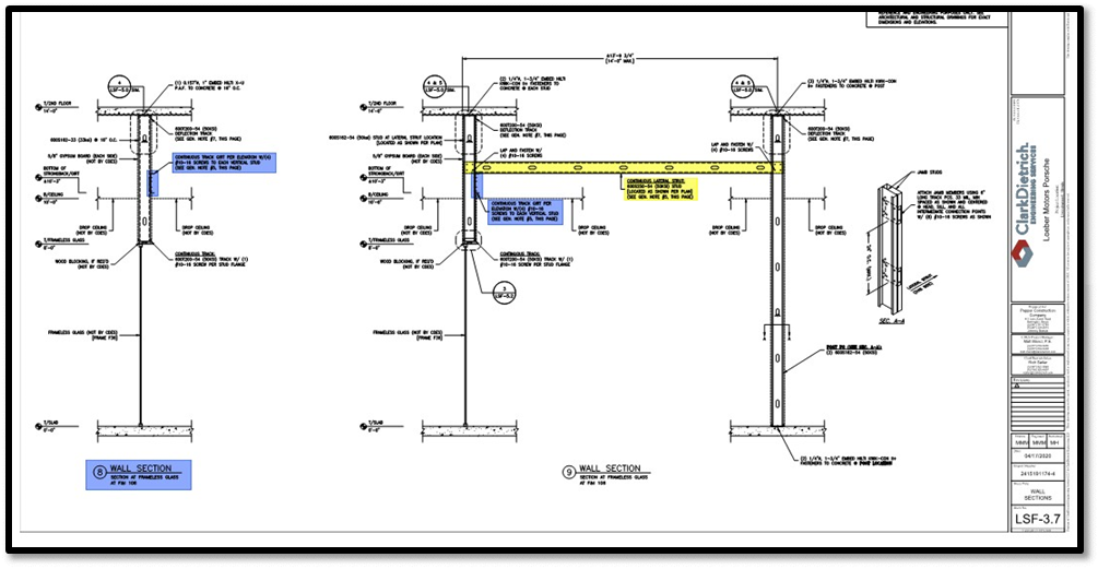
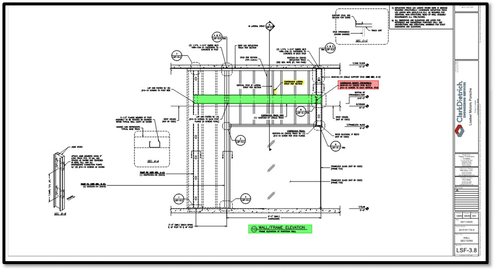
There were multiple rooms that included frameless glass partition walls, many of which had windows that turned corners and left no room for full height framing in the very corners of the respective rooms. While there was a drop ceiling in these areas, the frameless glass partitions could not accommodate any kind of vertical movement of the primary structure, which meant a typical kicked frame bulkhead suspended from the floor above would not be acceptable. As such, the deflection of the primary structure needed to be accommodated within cold-formed framing at the head of the wall framing and underside of the slab. CDES came up with a straightforward framing concept that involved the use of continuous strongbacks and girts to provide adequate support for the weight of the wall framing over the frameless glass partitions while still providing a clear load path for all the interior lateral loading as well. These strongbacks/girts in turn were supported by full-height posts. The basic free-body diagram of the strongback/girt was a simple span beam with a cantilever. By utilizing both studs AND tracks as strongbacks/girts, CDES was able to provide details that resulted in structurally sound connections at all the respective intersections of these elements, such as stud strongback to fit inside track strongback. Fortunately, most of these rooms had repetitive framing conditions, which helped to streamline some of the engineering efforts. However, during the design process, an addendum was issued which significantly widened one of the side frameless glass partitions (Figure 1). At this location, needing to utilize every space of wall and minimize the lengths of the cantilever(s), an additional lateral strut needed to be added (Figure 2 - additional lateral strut noted in yellow). While the overall concept is relatively simple/straightforward, clearly depicting all information on a 2-D set of shop drawings required some additional artistry (no BIM or 3-D modeling was used). To help portray all of this to the carpenter, CDES needed to include multiple plans, sections and elevation views. Furthermore, CDES was intentionally diligent with the naming convention throughout the shop drawings for all the respective elements such as gravity strongback, track girt and lateral strut. Below are some additional screenshots from the cold-formed steel shop drawings, color- coded from the framing plan for added clarity.
|

