2024 CFSEI DESIGN EXCELLENCE AWARD WINNERS
HONORABLE MENTION
EXCEL ENGINEERING, INC.
FLEXJET
RICHMOND HEIGHTS, OHIO
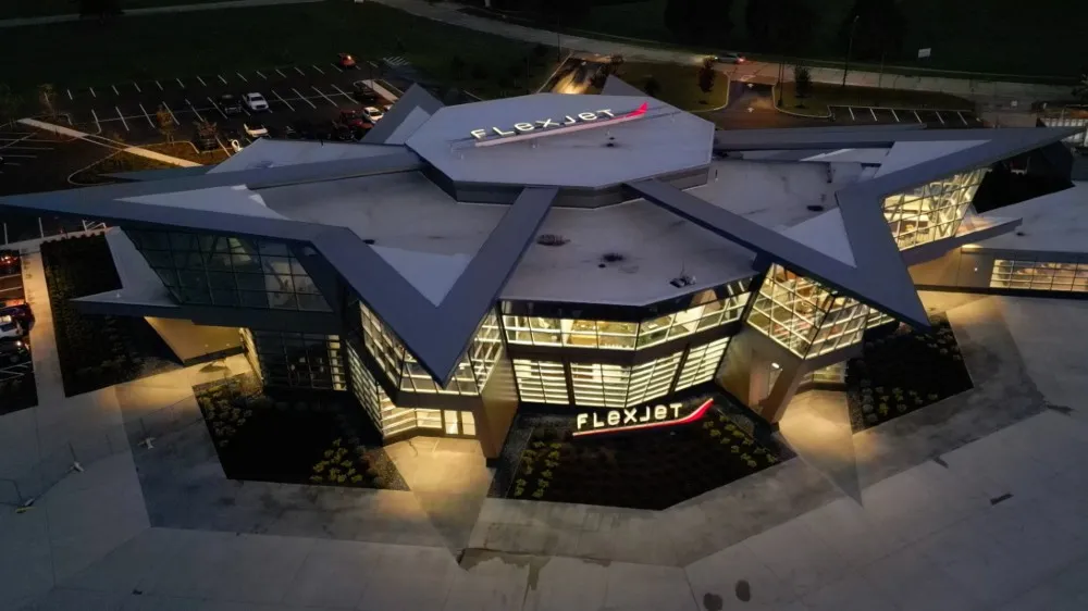 FlexJet FlexJet
26000 Curtiss Wright Parkway
Richmond Heights, OH 44143
Completion Date: Sept 2023
Construction Cost: $50 Million
Owner: Flexjet
Architect of Record: Richard Hebard, Richard D. Hebard Architect
Engineer of Record for Structural Work: Daniel J. Schenkel, Engineering Resources, Inc.
Cold-Formed Steel Specialty Engineer: Erik Johnson, Excel Engineering, Inc.
Cold-Formed Steel Specialty Contractor: Jason Dalessandro, JLJI Enterprises, Inc.
Award Entry Submitted by: Erik Johnson, Excel Engineering, Inc.
Project Background
 The Flexjet global headquarters project involved the design of the exterior cold-formed steel (CFS) framing and the CFS framing for an interior tiered platform. The building, located at the Cuyahoga County Airport in Richmond Heights, Ohio, is two stories with unique CFS framing details. The super-structure is structural steel with concrete/precast floors and metal roof deck. The building includes over 50,000 square feet of office space. The Flexjet global headquarters project involved the design of the exterior cold-formed steel (CFS) framing and the CFS framing for an interior tiered platform. The building, located at the Cuyahoga County Airport in Richmond Heights, Ohio, is two stories with unique CFS framing details. The super-structure is structural steel with concrete/precast floors and metal roof deck. The building includes over 50,000 square feet of office space.
Design Challenges and Solutions
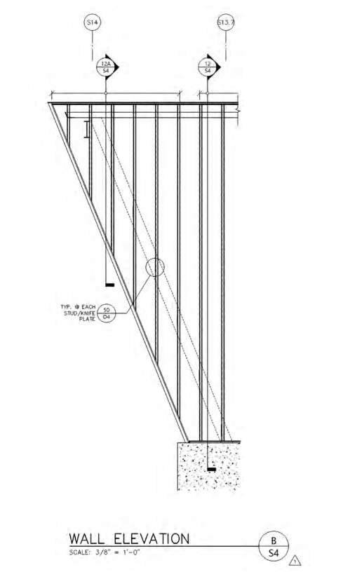
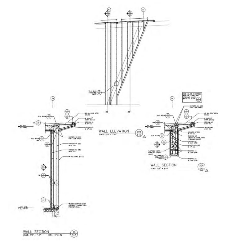
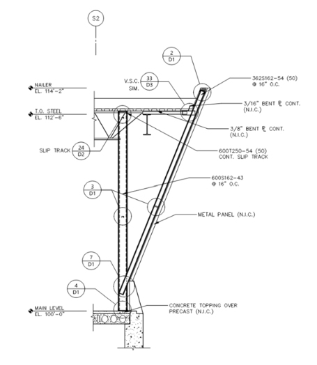
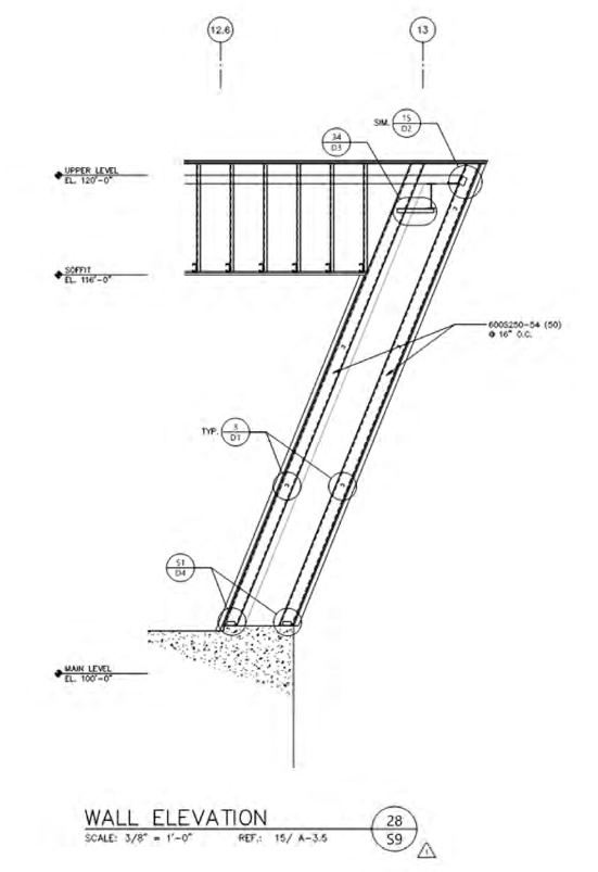
The building has a lot of sloping framing and special framing details. Figure 1 shows a detailed elevation of one area with sloping studs. Here, Excel Engineering, Inc., designed a stud sill to span in the weak direction to support the weight of typical stud framing above, and in the strong direction to support out of plane wind loads.
Excel Engineering worked directly with the EOR to provide a special detail at the sloping stud sill, as the structural angle ended before the built-up sill framing. Excel Engineering was able to get a knife plate installed between the double studs the CFS attached to, which supported vertical and lateral loads.
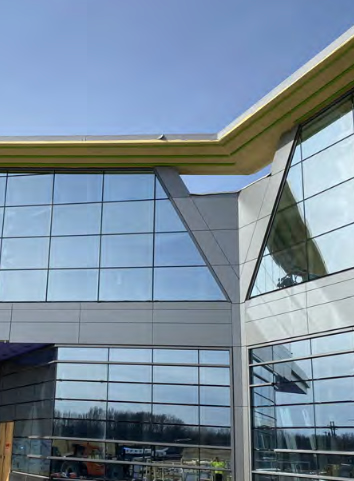
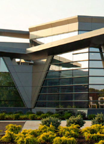
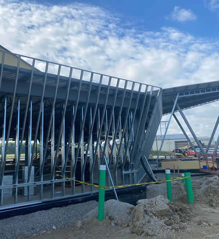
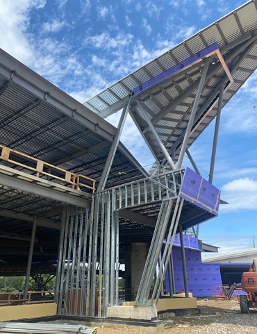
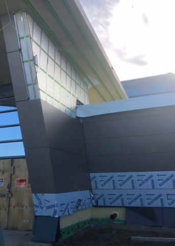
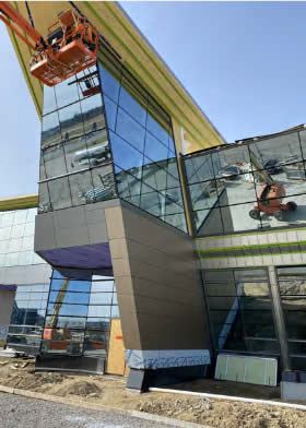
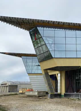
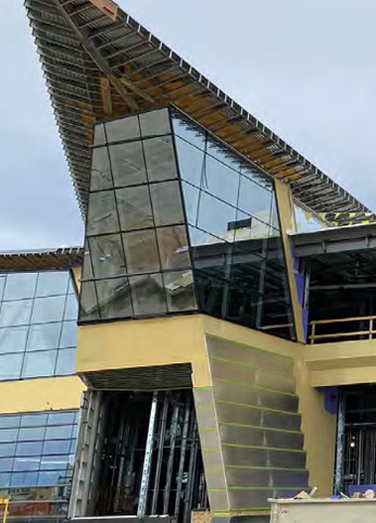
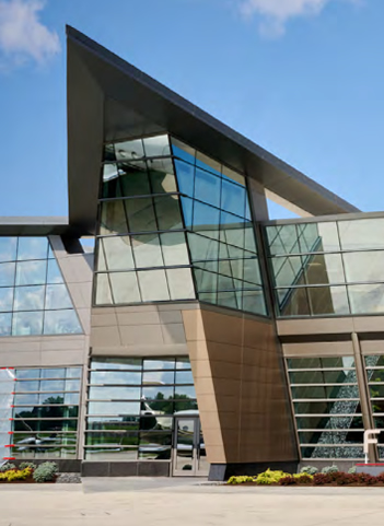
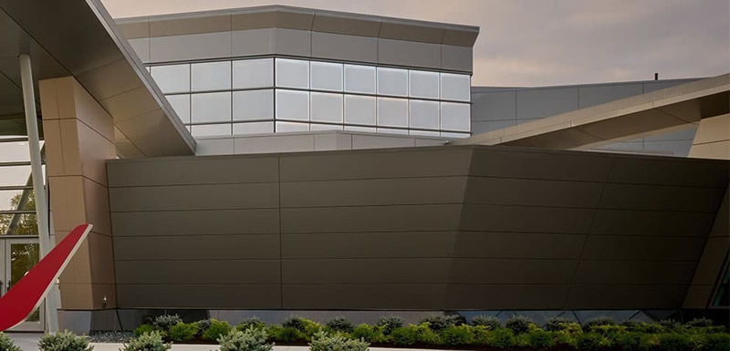
The sill width was another constraint as there is curtainwall glazing on one side and an open-air pass through on the other. Figure 2 shows the as-built framing prior to the curtainwall being installed. Figure 3 shows the almost finished building detail, and Figure 4 shows the finished building detail. Given the shape of the building, with its many sharp corners, several CFS framing sections had to be designed as sloping framing.
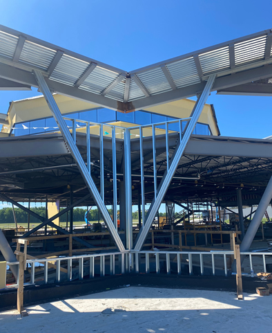 Figure 5 shows engineered drawing section for typical sloping wall framing. Figure 6 shows the as-built framing, and Figure 7 presents the finished building detail. Figure 5 shows engineered drawing section for typical sloping wall framing. Figure 6 shows the as-built framing, and Figure 7 presents the finished building detail.
Several wingwalls had to be designed to accommodate the sloping framing. The wingwalls required different detailing depending on the geometry of the walls. Figures 8-10 present the engineered drawing sections of the typical wingwall framing.
Due to the use of round tube steel, Excel Engineering again worked with the EOR to have structural steel knife plates to support floating CFS framing for details in Figures 8-9. See Figure 11 for as-built framing and see Figures 12-15 for in-progress images. Figure 16 shows the wingwall framing finished build.
In addition to coordination with the EOR, there were several meetings with JLJI to discuss detailing to ensure framing was installed per design drawings.
|
