2023 CFSEI DESIGN EXCELLENCE AWARD WINNERS
MUNICIPAL/CULTURAL - FIRST PLACE
MCCLURE – BLESSED STANLEY ROTHER SHRINE
OKLAHOMA CITY, OKLAHOMA
Blessed Stanley Rother Shrine
700 SE 89th St.
Oklahoma City, OK 73149
Completion Date: December 2022
Completion Date: $50 million
Owner: Catholic Archdiocese of Oklahoma City
Architect of Record: Arthur C. Lohsen, Frank & Lohsen Architects
Engineer of Record for Structural Work: David J. Oleynik, Spiegel Zamecnik & Shah
Cold-Formed Steel Specialty Engineer: Joshua Garton, P.E., McClure
Cold-Formed Steel Specialty Contractor: Carl Wedell, Radius Track Corporation
Award Entry Submitted by: Lauren Gutknecht, McClure
Project Background
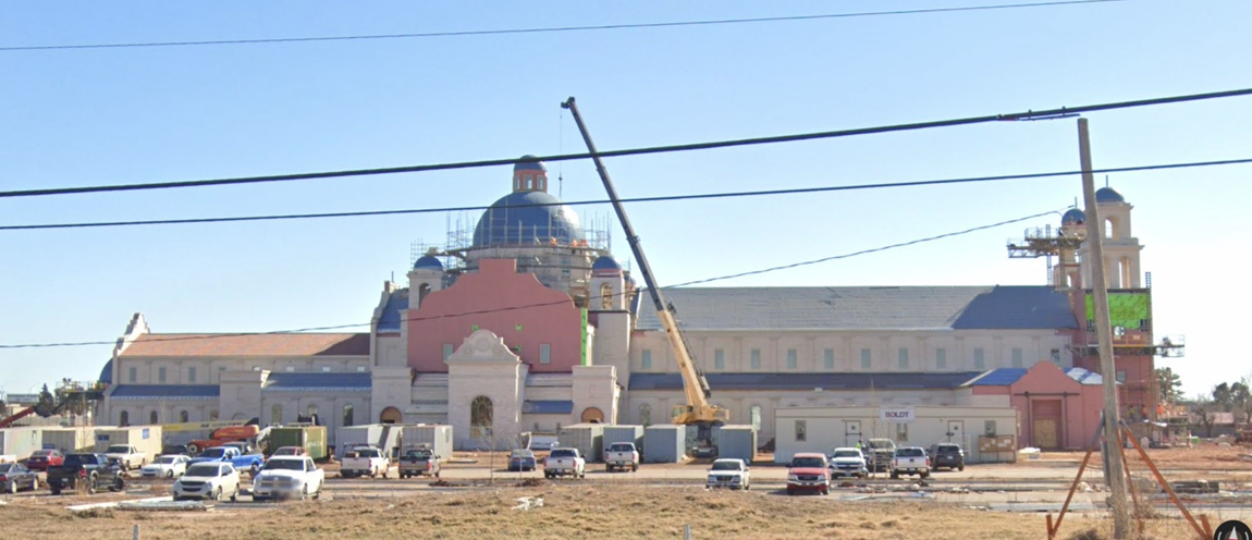
The Blessed Stanley Rother Shrine is a two-story steel-framed Church in Oklahoma City. The facility is a new 40,000-square-foot structure that displays ornate details, towers, clerestory, interior and exterior domes, as well as interior barrel vaults and pendentive framing.
Design Challenges and Solutions
McClure's scope was to assist Radius Track Corporation in the design and detailing of the complex curved framing of the:
- Main 40-ft.-diameter self-supporting dome, which supported an octagonal windowed cupola and secondary 11-ft.-diameter dome, which in turn supported an 11-ft.-tall finial.
- Two smaller 10-ft.-diameter self-supporting domes that were supported by 1'6"-tall knee walls.
- A 25-ft.-diameter half dome, with a diverging diameter interior dome, with horizontal support penetrating the brick cladding system.
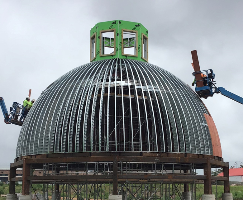
- Interior pendentive and arch framing to support decorative millwork. Figure 1 shows the construction of the project.
Main Dome Framing:
The 40-ft.-diameter main dome is a cold-formed steel stud framed self-supporting load bearing system comprised of load bearing crimped studs combined with structural steel laser cut steel plate circular tension ring, and laser cut custom-curved structural steel built-up compression box ring.
 The main dome posed several unique issues, most of which were related to cupola framing. The first issue was that the cupola, in order to meet architectural considerations, is hollow to allow the clerestory window light through the main dome. A traditionally framed dome would have center spokes to brace the interior of the compression ring against rotation and provide load transfer across the center of the dome from lateral loads. The second issue was that the cupola at the center of the dome has significant additional loads. The cupola finish system is 13,000 lbs. of solid stone (in addition to cupola weight). The cupola's lateral system is cold-formed steel window jambs with X-braced straps between the posts above and below the headers, adding point loads to the compression ring, along with significant overturning forces on the compression ring. The main dome posed several unique issues, most of which were related to cupola framing. The first issue was that the cupola, in order to meet architectural considerations, is hollow to allow the clerestory window light through the main dome. A traditionally framed dome would have center spokes to brace the interior of the compression ring against rotation and provide load transfer across the center of the dome from lateral loads. The second issue was that the cupola at the center of the dome has significant additional loads. The cupola finish system is 13,000 lbs. of solid stone (in addition to cupola weight). The cupola's lateral system is cold-formed steel window jambs with X-braced straps between the posts above and below the headers, adding point loads to the compression ring, along with significant overturning forces on the compression ring.
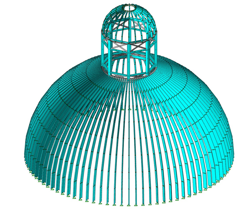
Both of these issues were accommodated by a fully detailed finite element model in RISA 3D. This model evaluated capacity of the framing members including derating factors for crimped studs, the reduced moment of inertia of the crimped studs for deflection, and the contribution of the plywood sheathing to stiffness of the system for deflection evaluation. Plate elements were used to apply loads that have the precise tributary areas on each member to produce the most efficient design. See Figure 2 for a visualization of the finite element model (plate elements are not shown for visual clarity). The second solution to the cupola loading was to include a structural steel built-up plate box compression ring to create torsional stiffness, and better disperse the load between the individual stud ribs. This allowed all ribs to be cold-formed steel and fully support the nearly 18,000 lbs. of structure above. This kept the entire dome structure comprised (by weight) of 93 percent cold-formed steel. Refer to Figure 3 for a visualization of a dome section.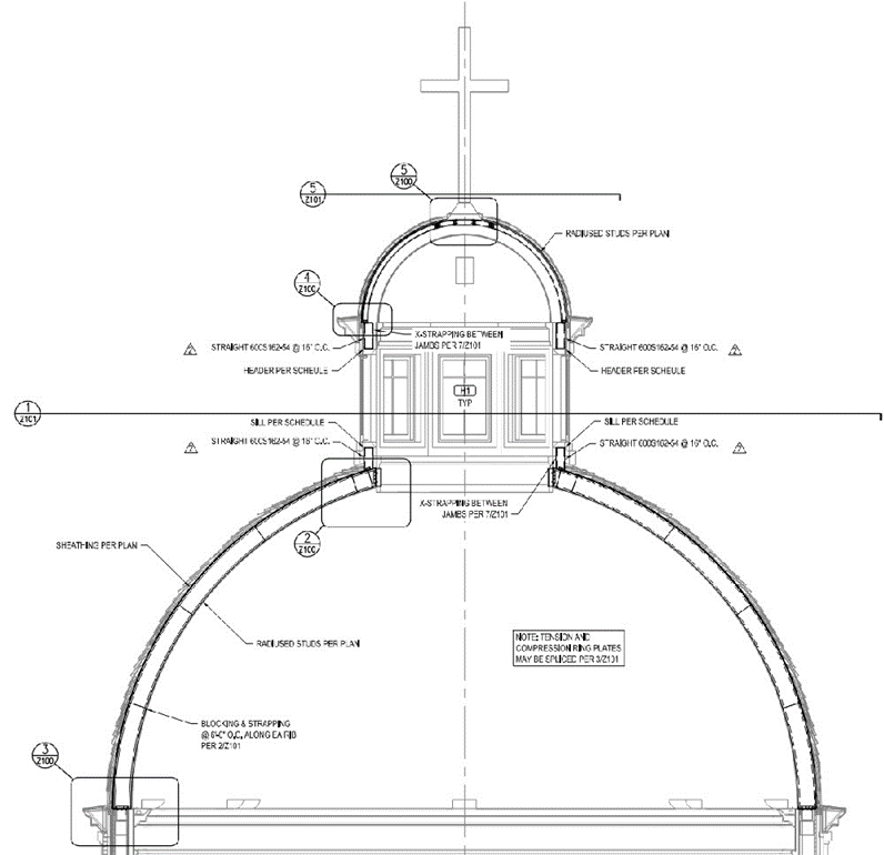
Small Dome Framing:
The small domes were relatively traditionally framed but had the added complexity of hoisting engineering included for the complex surface (again covered by a full finite element model in RISA 3D). The complexity is that they sit on short straight walls that are separate from the dome system. They were designed similar to shear walls, using a 3D model to disperse the load. With the forces being relatively small, gypsum wallboards were utilized to support the lateral loads. Both small domes had cast stone finials that the dome had to axially support, as well as the added horizontal loads.
Half Dome:
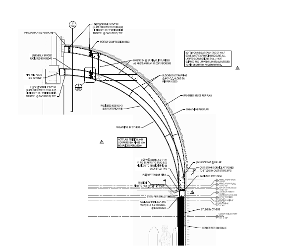
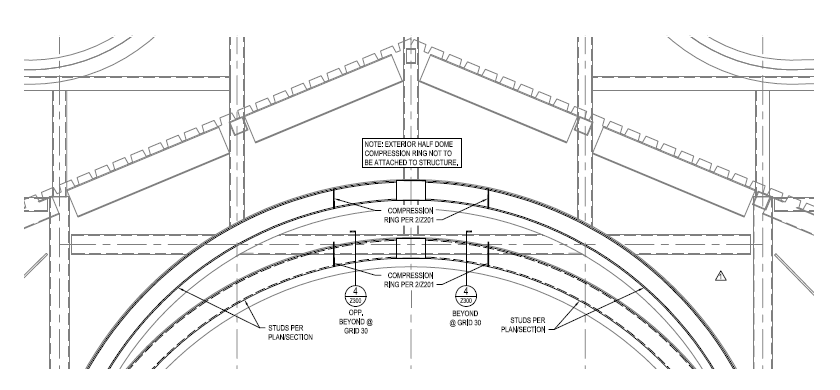
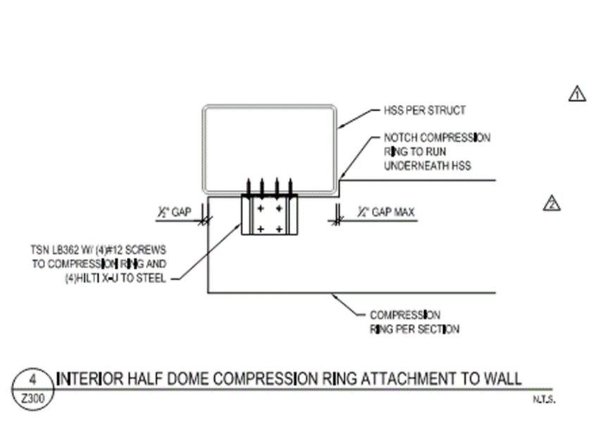
 The half dome's complexity is that the compression ring at the top of the dome was not permitted to penetrate the brick finish. To laterally support the half dome, the interior finish dome was used (as it was a separate curved surface). The two domes were then tied together vertically and laterally at the top so that the resultant thrust could be transferred at the center point of the half dome. A tension ring at the bottom acted as a vertical load distribution member, as well as a wind girt to transfer forces back to the structure. See Figures 4,5, and 6 for the half dome section, elevation of attachment, and resultant attachment to structural steel. The half dome's complexity is that the compression ring at the top of the dome was not permitted to penetrate the brick finish. To laterally support the half dome, the interior finish dome was used (as it was a separate curved surface). The two domes were then tied together vertically and laterally at the top so that the resultant thrust could be transferred at the center point of the half dome. A tension ring at the bottom acted as a vertical load distribution member, as well as a wind girt to transfer forces back to the structure. See Figures 4,5, and 6 for the half dome section, elevation of attachment, and resultant attachment to structural steel.
Interior Pendentive:
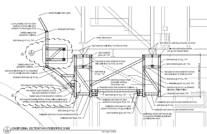
While on uniform surfaces, there are many different directions and spans of framing that require complex coordination between all surfaces. All required 3D model coordination and detailed coordination of the surfaces, as well as unique load paths and connection evaluation. A 3D finite element model was made for these areas. See Figure 8 for pendentive framing examples.
This complicated curved structure showcases McClure's significant experience and expertise at curved cold-formed steel structures, pushing the limits and boundaries of cold-formed steel to solve complex and unique problems.
|
