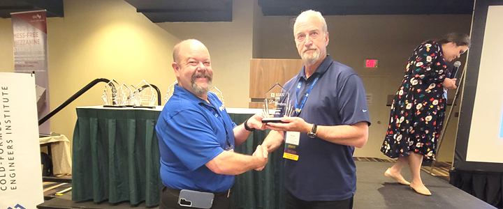
2023 CFSEI DESIGN EXCELLENCE AWARD WINNERS
SECOND PLACE - RESIDENTIAL/HOSPITALITY
R.A. SMITH, INC. – THE ROSIE
CHICAGO, ILLINOIS
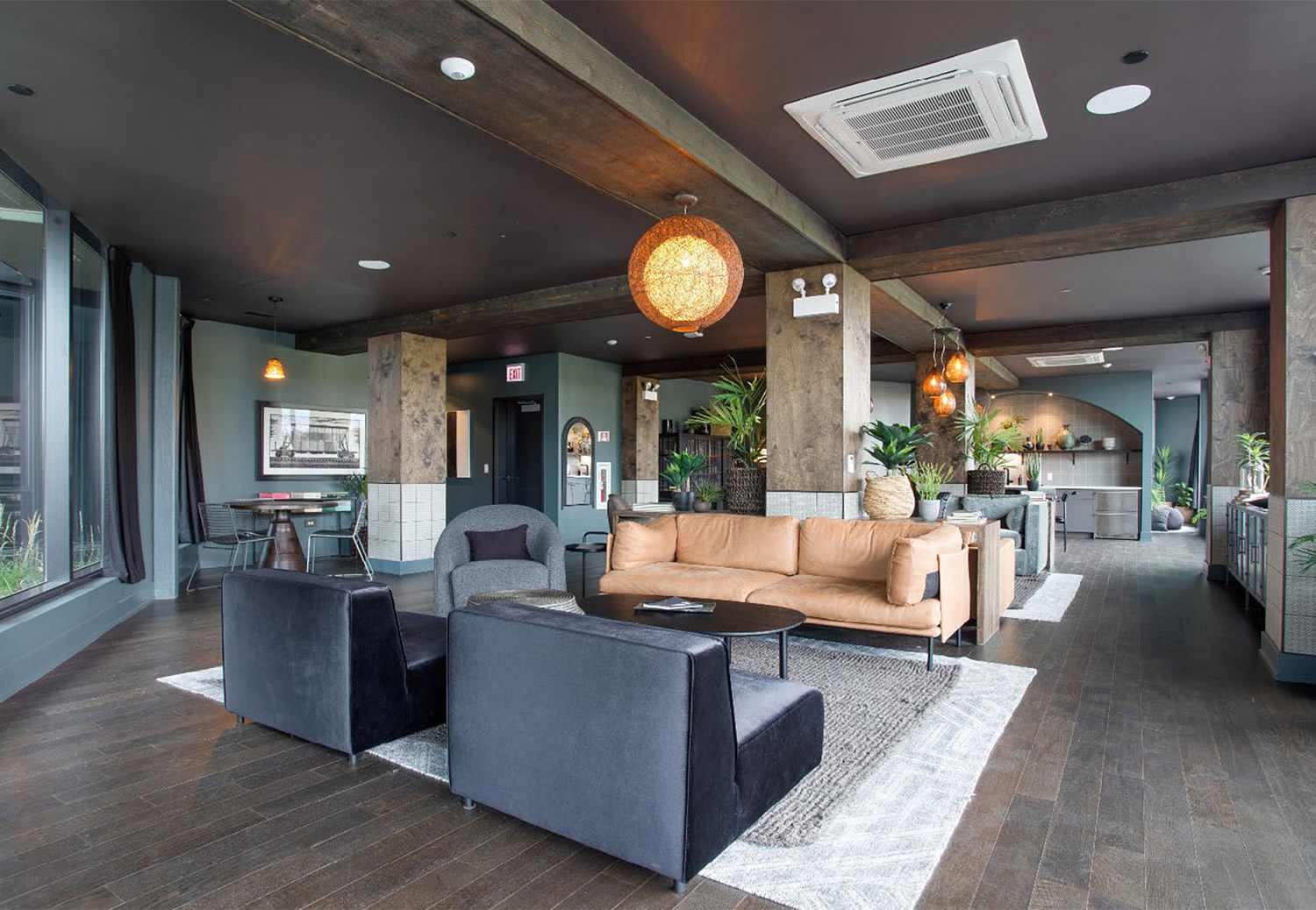 The Rosie The Rosie
1461 S. Blue Island Street
Chicago, IL 60602
Completion Date: November 2020 (Top Out/Dry In)
Construction Cost: $41 million
Owner: Cedar Street Companies
Architect of Record: Dan Retzner, AIA, Hartshorne Plunkard Architecture
Engineer of Record for Structural Work: Steve Franckowiak, S.E., P.E., Forefront Structural Engineers Inc.
Cold-Formed Steel Specialty Engineer: Patrick W. Ford, P.E., S.E., R.A. Smith, Inc.
Cold-Formed Steel Specialty Contractor: Jason Brown, Denk & Roche Builders.
Award Entry Submitted by: Patrick W. Ford, P.E., S.E., R.A. Smith, Inc.
Project Background
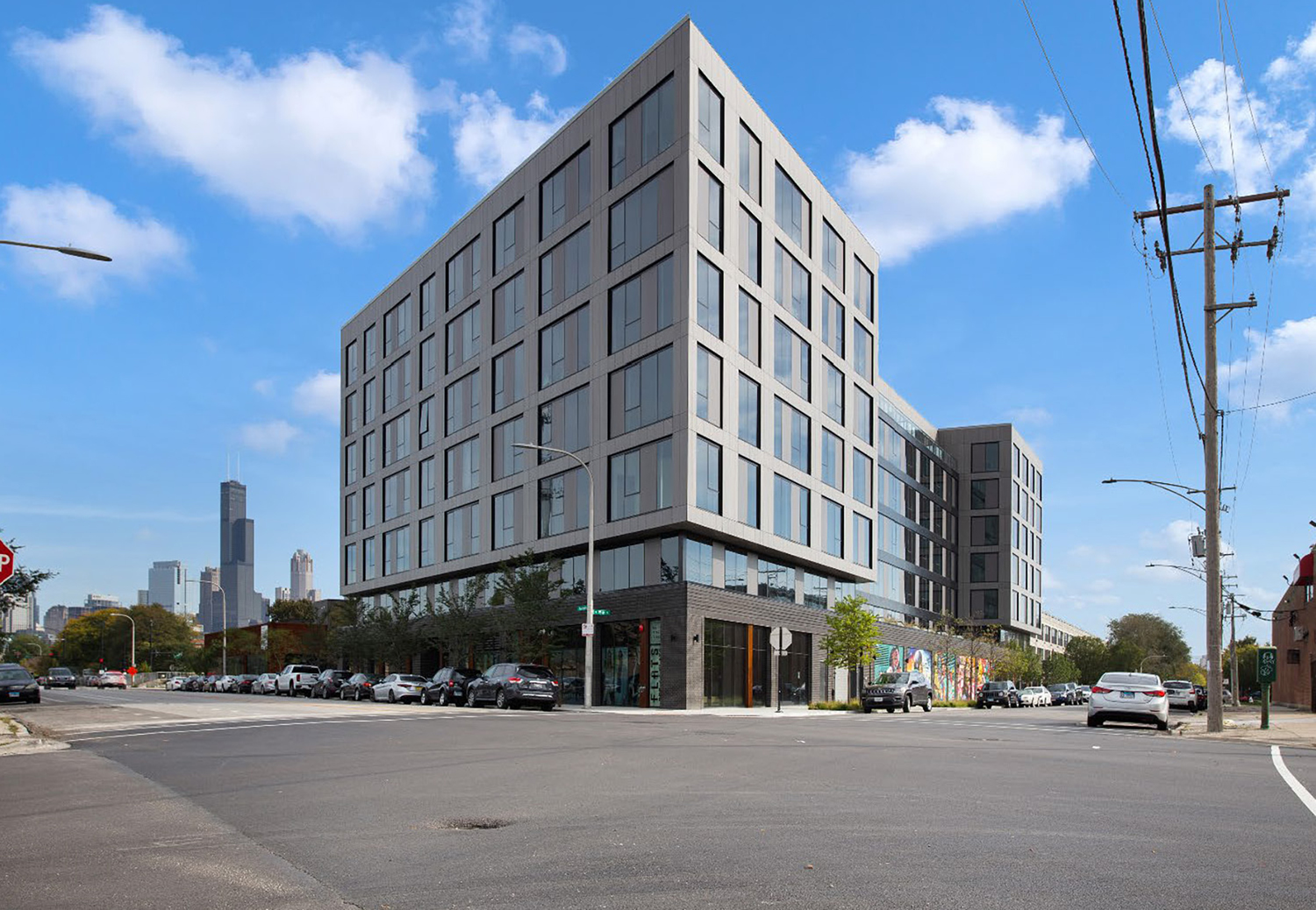
 Architecturally, The Rosie apartment project from Cedar Street Development provides 202 luxury residential units, two high-level retail spaces and parking in an amenity-packed site. This project is groundbreaking for its design and magnitude in this location. The Rosie is surrounded by Pilsen to the south, Little Italy to the north, and the Illinois Medical District and University of Illinois-Chicago to the west. It is close to downtown Chicago, the South Loop, Chinatown, expressways, and a variety of dining, shopping, and entertainment venues. Additionally, the site is adjacent to University Commons, the 1,000-unit high-end condominium/adaptive rehab for South Water designed in the Daniel Burnham style of the 1920s. Architecturally, The Rosie apartment project from Cedar Street Development provides 202 luxury residential units, two high-level retail spaces and parking in an amenity-packed site. This project is groundbreaking for its design and magnitude in this location. The Rosie is surrounded by Pilsen to the south, Little Italy to the north, and the Illinois Medical District and University of Illinois-Chicago to the west. It is close to downtown Chicago, the South Loop, Chinatown, expressways, and a variety of dining, shopping, and entertainment venues. Additionally, the site is adjacent to University Commons, the 1,000-unit high-end condominium/adaptive rehab for South Water designed in the Daniel Burnham style of the 1920s.
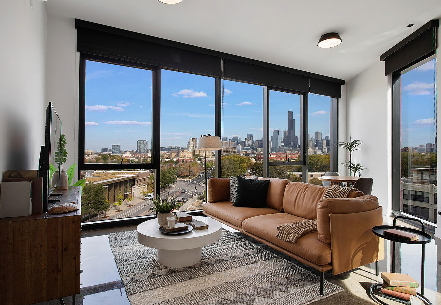
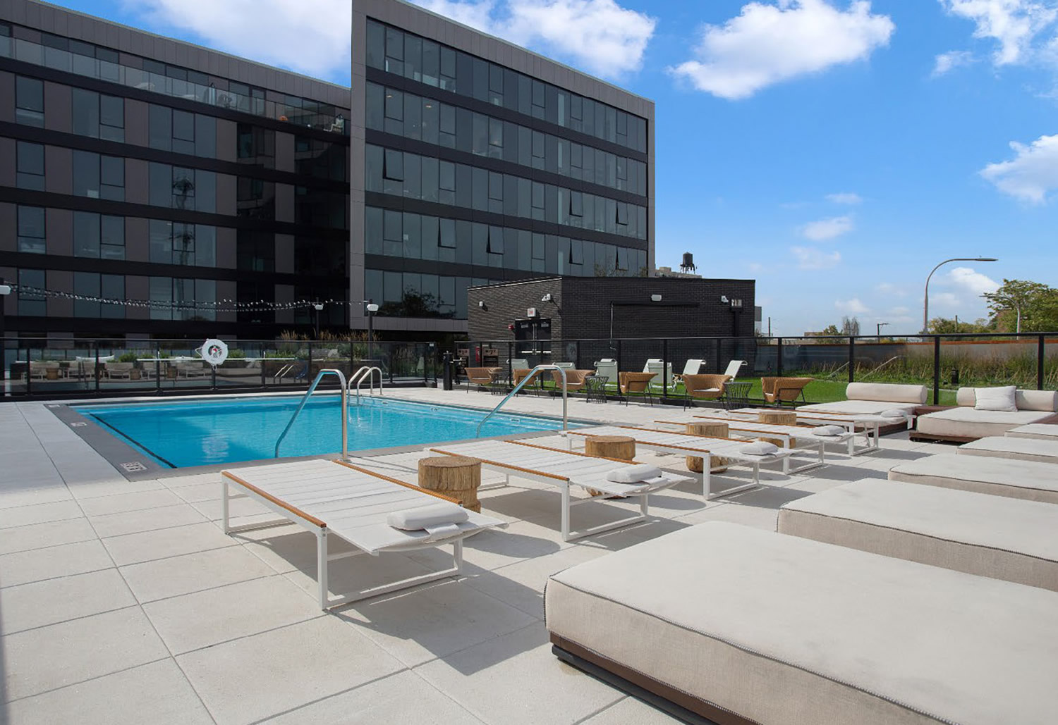
Additionally, The Rosie apartment project offers impressive views of the city with contemporary styling and the latest features. Many of the apartments are convertible with movable partitions and Ori technology in a variety of studio, one- and two-bedroom units. Floor-to-ceiling windows are typical. In-unit washers, dryers, dishwashers, and glass-enclosed rain showers are also featured. Amenities include a lobby lounge, club room, grass-covered roof deck, rooftop with indoor and outdoor lounge, large outdoor pool, grilling stations, and a fully equipped fitness center.
Structurally, the building is a total of seven stories. A large, one-story cast-in-place reinforced concrete podium is followed by six stories of cold-formed steel (CFS) framing. The overall primary lateral bracing of the structure is provided by cast-in-place concrete stair and elevator cores. The CFS framing includes both C-stud load-bearing and exterior wall framing, as well as CFS joists.
Design Challenges and Solutions
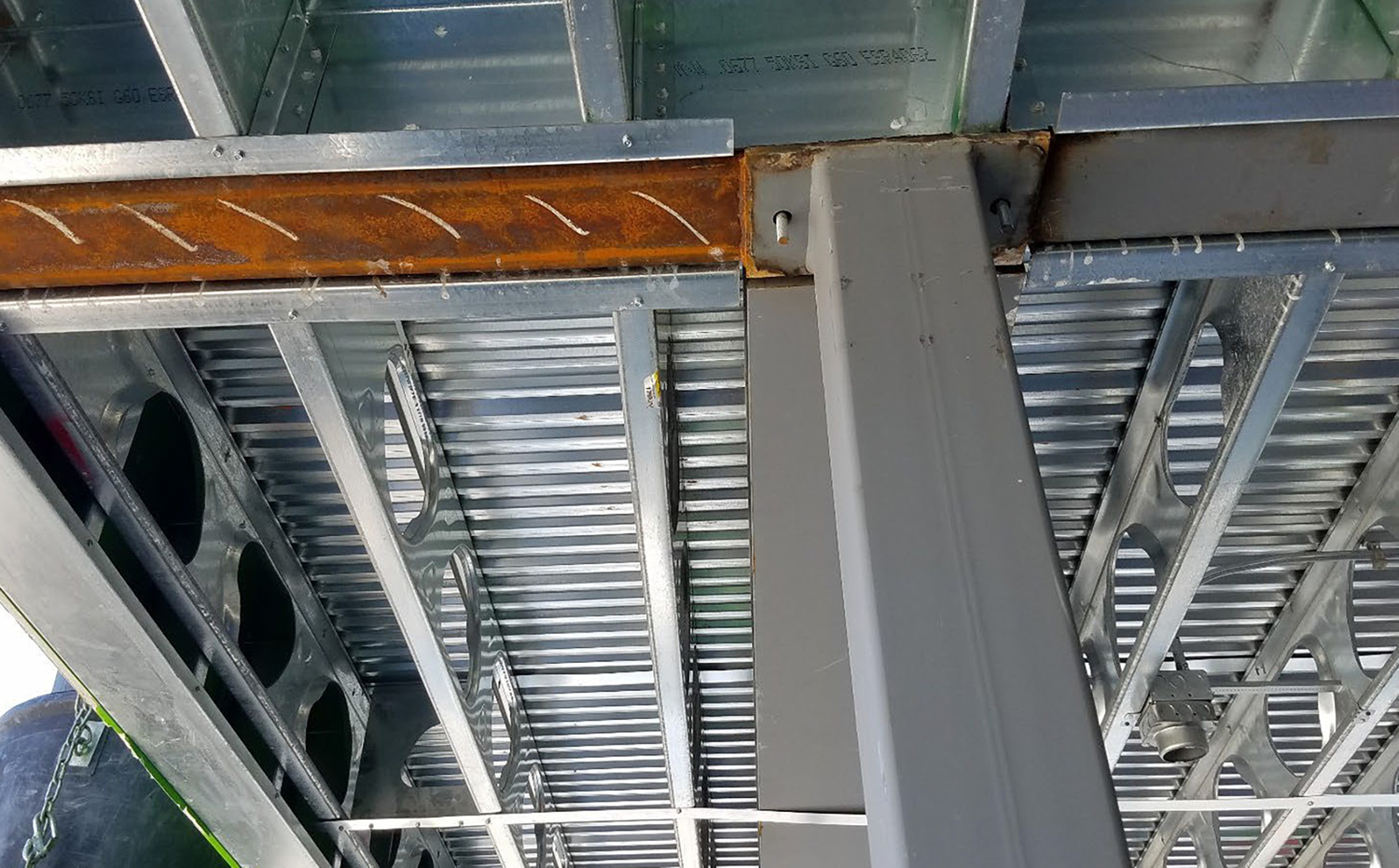
 The design is unusual in that it features a cantilevered third floor around virtually the entire perimeter of the apartment tower. This was accomplished by R.A. Smith, Inc. through a hybrid assembly of the CFS with hot-rolled steel transfer beams and columns (posts) concealed within the third-floor cavity and second-story walls. Further complicating the structural design is the “H”- shaped overall plan that includes one of the outer wings at an acute angle from the rest of the tower. Architecturally, the second story is designed to be exclusively glass on the exterior. This necessitates the bearing walls to be perpendicular to the exterior wherever possible or for the support to be provided by additional steel beams with the floor cavity. The clean exterior and interior look of the building belies the complexities concealed with the second story and third floor. The design is unusual in that it features a cantilevered third floor around virtually the entire perimeter of the apartment tower. This was accomplished by R.A. Smith, Inc. through a hybrid assembly of the CFS with hot-rolled steel transfer beams and columns (posts) concealed within the third-floor cavity and second-story walls. Further complicating the structural design is the “H”- shaped overall plan that includes one of the outer wings at an acute angle from the rest of the tower. Architecturally, the second story is designed to be exclusively glass on the exterior. This necessitates the bearing walls to be perpendicular to the exterior wherever possible or for the support to be provided by additional steel beams with the floor cavity. The clean exterior and interior look of the building belies the complexities concealed with the second story and third floor.
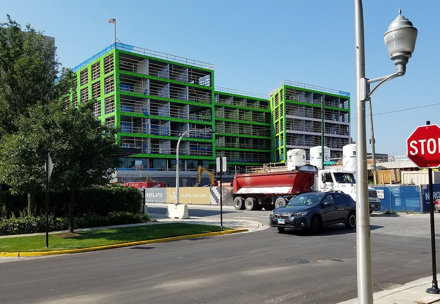
R.A. Smith, Inc. was hired at the onset of design to work directly with the architect and structural engineer of record (SER) to assist with these challenges as well as to provide the most cost-effective design prior to bidding. This also allowed all lateral and gravity transfer loads to be coordinated early on with the SER to create the most efficient podium, foundation, and core structures possible.
The rooftop fall arrest and window washing anchors are also designed into the CFS roof structure. This was completed by designing the joists at the specific locations for the significant applied lateral forces and movements, resolving any torsions into couple forces, and reinforcing all affected members accordingly. The detail is concealed within the roof joist cavity and finished above the roof with roof jacks and the necessary waterproofing.
 An additional CFS structural feature was the inclusion of the “skip hoist” or construction elevator support to be provided by the CFS upper structure. This elevator was supported for gravity loads primarily by a trussed tower bearing at the foundation level. This deals with most of the vertical load support, while the induced lateral and torsional support loads were resisted by the CFS above. This is a “means and methods” issue, and as such was contracted separately by R.A. Smith, Inc. with the general contractor. The elevator tower shop drawings with loads were submitted to R.A. Smith, Inc., including the hot-rolled steel struts with desired attachment heights (typically at or near alternating stories and aligning with panel points on the trussed tower), and any minimum anchorage thickness requirements. Since the struts are rarely perfectly horizontal and the elevator is eccentric to the tower, additional vertical forces are induced, and significant lateral (including storm) forces have to be resisted by the CFS structure. This would sometimes require reinforcing or increasing the perimeter member bending capacity, with the major lateral forces being resisted by the diaphragm strength of the CFS assembly. Since the installation by necessity must be completed before the structure is entirely finished, the bare deck strengths need to be relied on. The hot-rolled anchorage hardware and connections into the floor were typically welded and blocking or drag struts extended into the building to develop the required diaphragm strength to resist the loads. After construction was completed, these supplemental structural elements were simply abandoned with the CFS floor assemblies. An additional CFS structural feature was the inclusion of the “skip hoist” or construction elevator support to be provided by the CFS upper structure. This elevator was supported for gravity loads primarily by a trussed tower bearing at the foundation level. This deals with most of the vertical load support, while the induced lateral and torsional support loads were resisted by the CFS above. This is a “means and methods” issue, and as such was contracted separately by R.A. Smith, Inc. with the general contractor. The elevator tower shop drawings with loads were submitted to R.A. Smith, Inc., including the hot-rolled steel struts with desired attachment heights (typically at or near alternating stories and aligning with panel points on the trussed tower), and any minimum anchorage thickness requirements. Since the struts are rarely perfectly horizontal and the elevator is eccentric to the tower, additional vertical forces are induced, and significant lateral (including storm) forces have to be resisted by the CFS structure. This would sometimes require reinforcing or increasing the perimeter member bending capacity, with the major lateral forces being resisted by the diaphragm strength of the CFS assembly. Since the installation by necessity must be completed before the structure is entirely finished, the bare deck strengths need to be relied on. The hot-rolled anchorage hardware and connections into the floor were typically welded and blocking or drag struts extended into the building to develop the required diaphragm strength to resist the loads. After construction was completed, these supplemental structural elements were simply abandoned with the CFS floor assemblies.
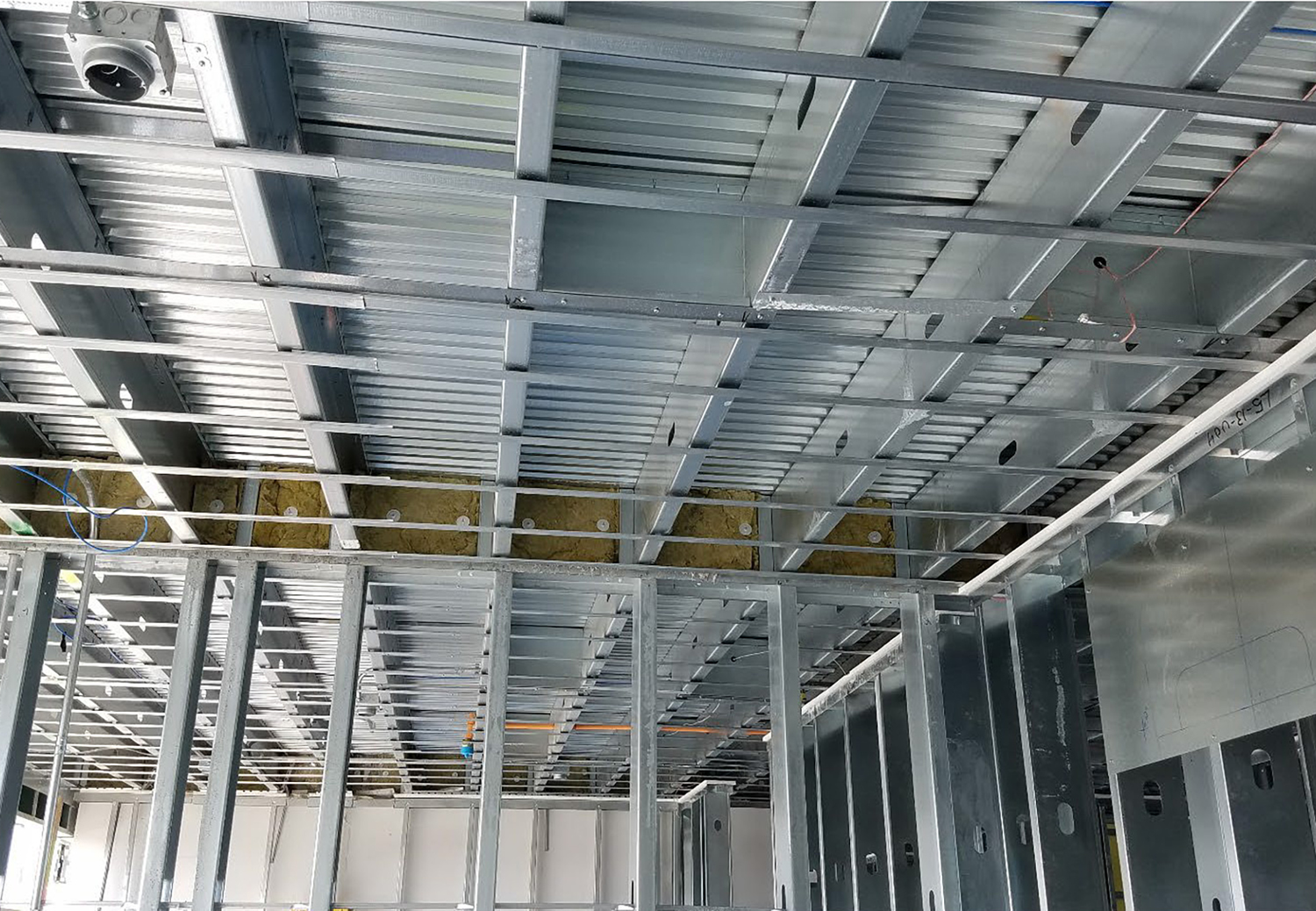 The deadloads for the project are typical of light framing, although the floors are not particularly lightweight since the featured floor finish is exposed (polished/sealed) concrete. The main exterior architectural finishes on the project are glass and architectural composite metal. CFS supported terraces are pavers over a membrane-protected insulated metal deck. Interior walls are all gypsum wall panel over CFS, and numerous assemblies include resilient furring and sound insulation. The deadloads for the project are typical of light framing, although the floors are not particularly lightweight since the featured floor finish is exposed (polished/sealed) concrete. The main exterior architectural finishes on the project are glass and architectural composite metal. CFS supported terraces are pavers over a membrane-protected insulated metal deck. Interior walls are all gypsum wall panel over CFS, and numerous assemblies include resilient furring and sound insulation.
Transient loads are likewise typical, although snow drift loads did, in some locations, exceed 56 psf (ASD). Unit loads are 40 psf, with other areas ranging up to 100 psf, and 125 at light storage areas. Wind loads were roughly 20 psf (primary) and 25 psf to 40 psf (secondary). Deflection limits used were typically L/360 for walls, L/600 for masonry, and L/480 (live load) for floor deflections..
Click here for shop drawings.
|
